

2.2 POWER SUPPLY CONNECTION
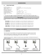
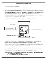
Before connecting the electrical supply to the DRO, please check the VOLTAGE SELECTOR switch to
see if correctly main supply voltage selected or not. Check Figure below for the position of the switch.
The
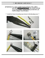
PROTECTIVE EARTH CIRCUIT
of the mains supply
MUST BE CONNECTED
to the earth grounding terminal
of the DRO through the supply cord
and
connected through an earth cable as per shown in Page 1.
The supply cord must be secured with cable ties to avoid from dropping into a hazardous position, for example
the floor or coolant tray, when disconnected from the DRO.
The supply cord must be routed away from moving parts, swarf, coolant or sources of heat.
III
POWER SUPPLY CONNECTION
If a mains plug is not already fitted to the supply cord or is of the wrong type, then a suitable EARTHED plug
should be used which complies with the relevant specifications for plugs and socket-outlets.
The specification of the mains supply fuse is
T0.5A, 220V
. It can not be replaced by operator. If the fuse blows
it is a possible indication of some significant problem with the power source.
Check the supply and wiring carefully. When replacing the fuse, the DRO must be first disconnected by removal
of the IEC socket from the inlet. For this connector is the primary disconnect device, do not place the DRO in the
place where is difficult to reach and make sure that the plug must be accessible all the time.
NOTE: 1. If the DRO is used in a manner not specified by the manufacturer, the protection provided
by the equipment may be impaired.
2. Non-professionals do NOT open the cover or repair
check if correct main
supply voltage is selected
Earth Grounding Terminal
Transducer Connectors
Power Switch
Figure 2.3
Grounding Terminal
X
Fuse
Power Switch
Input Connectors
Voltage Switch
Main Power
Y
Z
Summary of Contents for ES-12
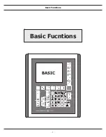
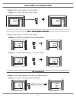
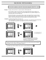
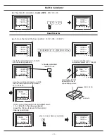
Page 8: ...1 Basic Fucntions Basic Functions BASIC...
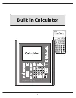
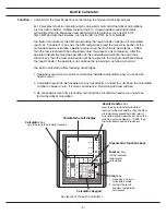
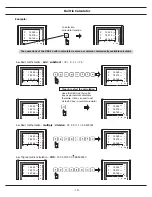
Page 15: ...8 Built in Calculator Calculator...
Page 27: ...20 REF datum memory...
Page 31: ...24 LHOLE tool positioning for the Line Holes...
Page 35: ...28 INCL Inclined angle tool positioning...
Page 40: ...33 PCD tool positioning for Pitch Circle Diameter...
Page 45: ...R R R 38 tool positioning for ARC machining...
Page 63: ...R R R 56 Simplified R function...
Page 73: ...66 Shrinkage Calculation L L X 1 005...
Page 91: ...Parameter Setup B 1 SET UP...