


Always Committed to Quality Technology & Innovation
Easson
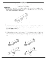
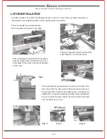
LATHE INSTALLATION
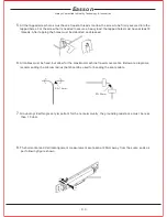
To install a readout on a lathe the following tips can be used. To mount the cross slide scale select a
flat surface that is suitable and clear of the travelling parts of the lathe.
The scale should be mounted insuring
that it is parallel and square to the slide.
Testing for parallel can be done by either
a dial indicator or a precision level
When mounting the reader head if necessary
pack the reader head so that it travels in line
and square to the scale to avoid any damage
to the scale.
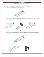
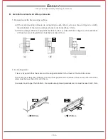
The longitudinal scale should be mounted on the back of the
lathe (Fig 1)with the open side of the scale facing down and
must be parallel to the bed. The reader head is mounted to the
saddle (Fig .2 & 3)via the brackets provided. Some modification
may be required for some lathes. Covers should be mounted
over the slides as per Fig 4
Fig .1
Fig .2
Fig .3
Fig .4
- C. 8 -
Summary of Contents for ES-12
Page 8: ...1 Basic Fucntions Basic Functions BASIC...
Page 15: ...8 Built in Calculator Calculator...
Page 27: ...20 REF datum memory...
Page 31: ...24 LHOLE tool positioning for the Line Holes...
Page 35: ...28 INCL Inclined angle tool positioning...
Page 40: ...33 PCD tool positioning for Pitch Circle Diameter...
Page 45: ...R R R 38 tool positioning for ARC machining...
Page 63: ...R R R 56 Simplified R function...
Page 73: ...66 Shrinkage Calculation L L X 1 005...
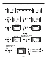
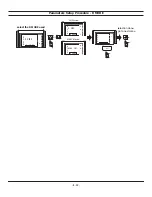
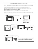
Page 91: ...Parameter Setup B 1 SET UP...