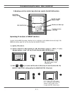


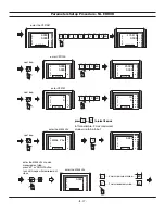

Parameters Setup Procedure - RAD/DIA
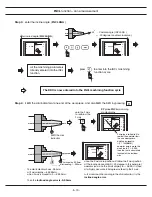
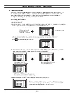
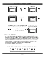
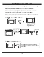
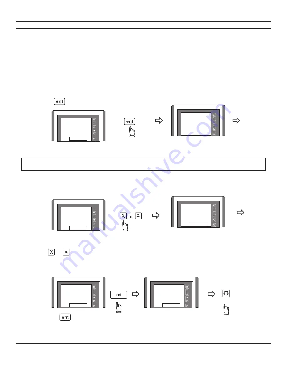
For example, if you want to make a change to the current 'rAd' display mode of the X axis, procedure are as follows
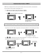
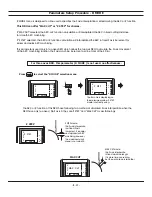
Press or to specify the X axis, if the current display mode is 'rAd', it will swap to 'dIA' after the key
press, and vice versa. The same procedure applied to Y , Z and U axis
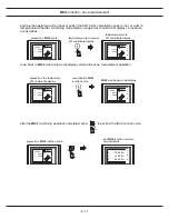
The X axis display mode have
been changed to Diameteral
display mode
then press to exist from
"RESOLU" menu and return to
the top level menu
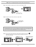
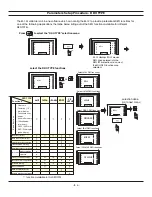
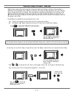
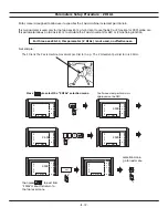
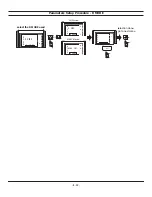
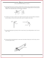
Press to select the "RAD/DIA" selection menu
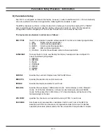
RAD/DIA menu is designed to allow operator to select the diemension display in Radius ( nromal display ) or
Diameteral ( 2X the real dimension ) display. This feature is very useful for lathe application. All axes in the DRO
can be configrured to DIA ( 2X ) display. If the axis display is configured as DIA display, a 'd' character will be
displayed at the first digit display of the axis to have the user easily recongise the display is in DIA mode. All
DRO functions that are normally used in lathe application are tested and confirmed to work properly under the
DIA display, such as INCL.
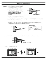
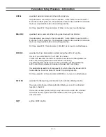
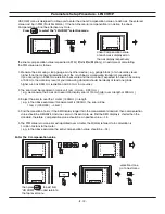
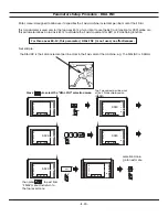
The RAD/DIA of the display axis are specified by 'rAd' or 'dIA' :
'rAd' - Radius mode display selected, axis shows the real dimension reading
'dIA' - Diameteral mode display selected, axis shows 2X( 2 times ) the real dimension reading.
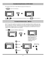
The 'rAd' display means Radius
display mode are selected in
the respective axis.
'rAd' represent Radius display mode, 'dIA' represent Diameter display mode. Press the "ent" key to make your selection
- B. 11 -
selection done
go to next menu
X
Y
Z
U
RAD/DIA
X
Y
Z
U
RAD/DIA
X
Y
Z
U
SEL.AXIS
rAd
rAd
rAd
rAd
X
Y
Z
U
SEL.AXIS
rAd
rAd
rAd
rAd
X
Y
Z
U
SEL.AXIS
dlA
rAd
rAd
rAd
X
Y
Z
U
SEL.AXIS
dlA
rAd
rAd
rAd
Summary of Contents for ES-12
Page 8: ...1 Basic Fucntions Basic Functions BASIC...
Page 15: ...8 Built in Calculator Calculator...
Page 27: ...20 REF datum memory...
Page 31: ...24 LHOLE tool positioning for the Line Holes...
Page 35: ...28 INCL Inclined angle tool positioning...
Page 40: ...33 PCD tool positioning for Pitch Circle Diameter...
Page 45: ...R R R 38 tool positioning for ARC machining...
Page 63: ...R R R 56 Simplified R function...
Page 73: ...66 Shrinkage Calculation L L X 1 005...
Page 91: ...Parameter Setup B 1 SET UP...