


X
Y
Z
ABS
mm
mm
mm
56.785
12.345
45.785
XS:
0 mm/min
X
Y
Z
ABS
mm
mm
mm
56.785
12.345
45.785
XS:
0 mm/min
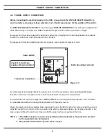
- 5 -
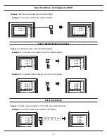
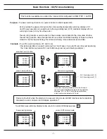
Basic Functions - SPEED [ axial cutting speed display ]
Purpose
: To make sure the machining surface finished is consistent, operator must know exactly how much the
machine travel speed is for the machining ( such as cutting, facing and etc.. ).
ES-12 provides the SPEED function to display the machine moving speed in
mm/min
in all selected axis.
The SPEED display is filtered by an 0.25 sec display filter to provide stabilized speed display, to enable
the operator to adjust the machine's power feed at a more easy and comfortable speed visualization.
The display resolution of the SPEED function is in
mm/min
, which is the most commonly used unit in
machine feed rate in CNC machining or cutting tool feed calculations. SPEED function is very useful in
monitoring many common machining process ( such as cutting, facing and etc.. ) to achieve
predictable surface finish or to achieve predictable cutting tool life.
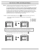
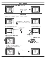
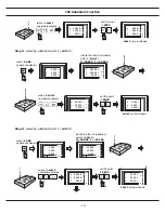
Example : To activate the SPEED display of X Axis, press Axis button for more than 0.6 sec. Then the
X moving speed display will be displayed in message window. Same operation for
Y, Z and U axis.
press for more than
0.6 sec.
XS - X SPEED display
YS - Y SPEED display
ZS - Z SPEED display
US - U SPEED display
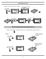
SPEED display mode
normal display mode
X
Y
Z
ABS
mm
mm
mm
56.785
12.345
45.785
X
Y
Z
ABS
mm
mm
mm
56.785
12.345
45.785
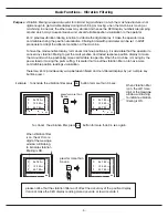
Please notice that during the SPEED display mode, all DRO functions are temporarily disable !
Operator have to exit the SPEED display mode to carry out any normal DRO functions
To exit the SPEED display mode and return to normal display mode, press
ce
ce
SPEED display mode
normal display mode
Summary of Contents for ES-12
Page 8: ...1 Basic Fucntions Basic Functions BASIC...
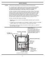
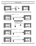
Page 15: ...8 Built in Calculator Calculator...
Page 27: ...20 REF datum memory...
Page 31: ...24 LHOLE tool positioning for the Line Holes...
Page 35: ...28 INCL Inclined angle tool positioning...
Page 40: ...33 PCD tool positioning for Pitch Circle Diameter...
Page 45: ...R R R 38 tool positioning for ARC machining...
Page 63: ...R R R 56 Simplified R function...
Page 73: ...66 Shrinkage Calculation L L X 1 005...
Page 91: ...Parameter Setup B 1 SET UP...