background image

63


Eagle Eye Power Solutions, LLC | 877-805-3377 | www.eepowersolutions.com 

II.

Definitions

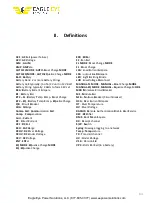
ACF 

AC F

ail (power failure) 

ACV 

AC V

oltage 

ALM 

AL

ar

AMP 

AMP

ere 

AUTO-FL MODE 

AUTO-FL

oat Charge 

MODE 

AUTO-EQ MODE 

AUTO-EQ

ualize Charge 

MODE 

Batt 

Batt

ery 

Battery Bank: 2 or more Battery Strings 
Battery Cell: typically: (1-of-6) 2V unit in 12V Batt 
Battery String: typically: 4 Batts to form 48V set 

BCA 

B

attery 

C

urrent 

A

mpere 

BF 

B

attery 

F

ail 

BTC 

 FL 

B

attery 

T

emp 

C

omp- 

FL

oat Charge 

BTC 

 EQ 

B

attery 

T

emp 

C

omp- 

EQ

ualize Charge 

C/B 

C

ircuit 

B

reaker 

CHA 

CHA

rge 

Comm. Fail 

Comm

unication 

Fail 

Comp

. : 

Comp

ensation 

Curr

. : 

Curr

ent 

DC 

D

irect 

C

urrent 

DCF 

DC F

ail 

DCH 

D

is

CH

arge 

DCOV 

DC O

ver 

V

oltage 

DCUV 

DC U

nder 

V

oltage 

DCV 

DC V

oltage 

ENT 

ENT

er 

EQ MODE 

EQ

ualize Charge 

MODE 

EQ 

EQ

ualize Charge 

ERR 

ERR

or 

FF 

F

an 

F

ail 

FL MODE 

FL

oat Charge 

MODE 

FL 

FL

oat Charge 

LCA 

L

oad 

C

urrent 

A

mpere 

LDA 

: output 

L

oa

D A

mpere 

LED 

L

ight 

E

mitting 

D

iode 

LVD 

L

ow 

V

oltage 

D

isconnect 

MANUAL-FL MODE 

MANUAL 

FL

oat Charge 

MODE 

MANUAL-EQ MODE

MANUAL 

Eq

ualize Charge M

ODE 

MCB :M

iniature 

C

ircuit 

B

reaker 

MF 

M

odule 

F

ail 

NFB 


N

F

use 

B

reaker (Circuit Breaker) 

OCA 

O

ver 

C

urrent 

A

mpare 

OT 

O

ver 

T

emperature 

OV 

O

ver 

V

oltage 

RADIUS: R

emote 

A

uthentication 

D

ia

l

-

I

U

ser 

S

ervice 

REC 

REC

tifier 

RMS 

R

oot 

M

ean 

S

quare 

RX 

R

eceipt channel 

S/W 

Sw

itch 

Syslog 

:Message logging to a network 

Temp 

Temp

erature 

TX 

T

ransmit channel 

UV 

U

nder 

V

oltage 

V1.0 

V

ersion 

1.0 

VPC : V

olts 

P

er 

C

ell (in a battery) 

Summary of Contents for DCPS-SHELF-9KW

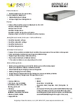
Page 1: ...height 19 inch wide configurable bullet style circuit breaker positions 2 Battery 10 Load Components of the DCPS SHELF 9KW Rectifier Shelf NESPACE KA Control Module NESPACE 48 3K Rectifier Module Accepts Bullet style 1RU Breakers for flexibility scalability The Appendix within this User Manual contains supporting documents including datasheets for the DCPS SHELF 9KW Rectifier Shelf modules and oth...

Page 2: ...5A bulk power or 6KW 111A in an N 1 redundant configuration and includes individual AC inputs for each rectifier module configurable circuit breakers for DC load and battery back up on the rear terminal block Each NESPACE 48 3K Rectifier Module provides a regulated 54Vdc output with up to 55 5A current see Figure 2 for derating below 176Vac The Rectifier Modules actively current share with other N...

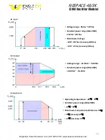
Page 3: ...is designed to operate in conditions with the applied AC input voltage between 85Vac to 285Vac Each Rectifier Module is capable of providing full DC Output power when the AC input voltage is 176V or higher Each Rectifier Module s DC output power derates when the AC input voltage is below 176V as shown below Figure 2 3KW Rectifier Module Output Power Derating vs AC Input Voltage Temperature Deratin...

Page 4: ...805 3377 www eepowersolutions com Read and review all portions of this Operation Manual before attempting to touch handle connect to or disconnect from configure power up power down or make any measurements to or from this Rectifier Shelf ...

Page 5: ...ax 166 5 55 5A 3 Modules 4 Output distribution ports 10 LOAD ports Battery 2 ports 5 Line Regulation over entire load range 0 5 0 27V 6 Load Regulation over entire line range 1 0 0 54V 7 Output current limit inception at 101 110 of full load 8 Output over voltage protection Module OVP shutdown at 59 0Vdc 0 5V 9 Battery Low Voltage protection LVD preset to 45 0V 0 5V user configurable 10 Output Rip...

Page 6: ...ltage 1 between input port and output port 1 5kVac 1 min or 2121Vdc 1 min 2 between input port and chassis 1 0kVac 1 min or 1414Vdc 1 min 2 4 Environmental Characteristics Operating Temperature Humidity 10 65 max de rates above 50 Operating Humidity 0 95 non condensing 2 5 Mechanical Dimensions Rectifier Shelf 177mm H X 482 6mm W X 469 1mm D 6 97in H X 19 0in W X 18 47in D Rectifier Module 122 5mm...

Page 7: ...SHELF 9KW and NESPACE Rectifier Modules in the shelf C Mechanical Loading Mounting of the equipment in a rack should ensure thata hazardous condition is not achieved due to uneven loading of therack D Circuit Overloading Consideration should be given to the connection of the equipment to the supply circuit and the effect of the overloading of circuits could have on over current protection and supp...

Page 8: ...es are installed by trained personnel Section 3 1 AC Input Cable Connections AC Input Terminal Blocks Located on the rear of the Shelf each of the 3 AC Input terminal blocks are dedicated to one of the three Rectifier Module positions AC Terminal Block 1 is dedicated to Rectifier Module position 1 only AC Terminal Block 2 is dedicated to Rectifier Module position 2 only AC Terminal Block 3 is dedi...

Page 9: ... is N1 N2 N3 AC Neutral 2 5mm2 AWG 12 L1 L2 L3 AC Line 2 5mm2 AWG 12 P E Frame Ground 2 5mm2 AWG12 Protective Earth Ground 8mm2 AWG8 Strip insert and tighten the proper sized wires N L and P E into the AC Input terminal block that physically supports the dedicated Rectifier Module RM for that position For example if only RM position 1 is configured within the Shelf then do not wire AC Terminal Blo...

Page 10: ...ut 25mm2 AWG4 Figure 6 DC Output Battery Terminal Block top view with cover removed DC Output GND Return for L1 L10 25mm2 AWG 4 Batt1 Batt2 54V 35mm2 AWG 2 Batt1 GND Batt2 GND 35mm2 AWG 2 Connect DC 54V cables with the straight barrel 2 hole lugs to the breaker protected L1 L10 Load and Batt 1 Batt 2 Battery nodes Also all of the Load Return and Batt Return cables should include straight barrel 2 ...

Page 11: ...te the L1 L10 load positions designed for up to 100A each the existing 1RU circuit breakers on the market are only rated up to 50A maximum At least 2 vendors have similar form factor 1RU bullet style breakers including Heinemann and Airpax see Figure 6a Note Any breaker position that is not filled with a circuit breaker should have a Breaker Blank Cover installed over that position Figure 6a Airpa...

Page 12: ...yle breaker current to 50A maximum Configuration settings are in the Web Browser interface and EDPS9K MAIN board DIP Switch settings see Item 3 below 2 EDPS9K MAIN board see Figures 6d Each switch on the 10 position DIP Switch links specifically to one of the 10 DC LOAD Breaker positions see Table 2 Any L1 L10 breaker position with a circuit breaker installed requires the linked DIP Switch positio...

Page 13: ...ted at the cable end within the heat shrink tubing so the mounting location is important The Batt Temp sensor needs to measure the ambient temperature near the Battery String so mount the Batt Temp sensor near the middle busbar on the Battery String Secure the Temp Sensor with a cable tie or other suitable method Batt Temp Rack Temp If possible Figure 7 Temperature Sensor connectors Avoid placing ...

Page 14: ...at shrink tubing over each ring terminal Remove the heat shrink to expose the ring terminals as needed to connect to the middle busbar on each Battery String This battery string midpoint connection essentially allows monitoring of a Left 2 string 27V and a Right 2 String that can be used for Equalization and determining battery health status If only one Battery String is used remove the heat shrin...

Page 15: ... Unused Normally Closed or Normally Open In that same page click the Alarm Set button to view alarms assigned to specific Dry Relays and to assign or delete alarms assigned to each Dry Relay Physical connections are made at the 12 position H W ALARM terminal block one pair of wires per Relay for up to 6 Dry Relay contact alarms The quick connect spring lock terminal block allows for fast installat...

Page 16: ...gure each Digital Input position using the dropdown menu choices are Unused Normally Closed or Normally Open Also the 6 Digital Input alarm items can individually given a name up to 12 characters long in Section 4 35 Digital Inputs Name Set page Physical connections are made at the 12 position EXT ALARM terminal block one pair of wires per Relay for up to 6 Digital Input alarms The quick connect s...

Page 17: ...ce Login Access to the Rectifier Shelf using the Web Server Interface GUI Main Page elements Alarm Manager Rectifier Manager SystemOperation Controller Manager System Configuration Measurement Set Date Time Set Controller Set Factory Initalization Alarm Log Data Log and Event Log Exiting the Web Server Interface ...

Page 18: ...s must be set to 192 168 0 xxx such as 192 168 0 100 with Subnet Mask 255 255 255 0 and Gateway192 68 0 1 Note the direct connection is established between Shelf and PC The 2nd step is to use the direct connection to edit the Shelf IP Settings so an active LAN connection is established with the Shelf 4 Open a browser such as Firefox or Chrome and in the address bar enter the numerical Shelf IP add...

Page 19: ...ect a network interface cable from the PC laptop to a separate port on the same LAN 3 On the Control Module panel press ENTER several times to view the Shelf IP address on the LCD screen The PC network settings will need to match this IP address to connect 4 Open a browser such as Firefox or Chrome and in the address bar enter thenumerical Shelf IP address The User Login page will open see Figure ...

Page 20: ...work Refer to Section 4 1 as needed 1 A failed LOGIN will result in a browser time out and should provide a time out message such as 2 A successful LOGIN will open to the Web Browser Interface to the Rectifier Home page which defaults to the Status Information Measure page see Figure11a This page shows real time measured values for AC Input Voltage DC Output Voltage and Load Current Rack Temperatu...

Page 21: ...IN always opens the Status Information Measure page which is also the default page for the HOME button Clicking the HOME button will always jump to the Status Information Measure page Menu Items Expanded Most Menu Items in these sections are for information only and are configurable from other pages Configuration or Alarm Set pages Menu Items in these sections are for configurable features and opt...

Page 22: ...tion Alarm This page displays the status of all configured alarms as either Normal green indicating no alarms are activated or Alarm red indicating an alarm is activated Setting alarm parameters and specific alarms on or off are explained in detail in the Configuration and Alarm Set sections Figure 11c Status Information Alarm page ...

Page 23: ...ns in the Shelf including Rectifier Module DC Output Voltage Rectifier Module DC Output Current Rectifier Module internal temperature in C Alarm status either Normal green indicating no alarms are activated or Alarm red indicating an alarm is activated Setting filled Used or open Unused Rectifier Module positions 1 2 and 3 is done in the Alarm Set RECT Used Unused section Figure 11d Status Informa...

Page 24: ...t Charge Voltage value between 42V 58V EQ VOLT Equalize Boost Charge Voltage value between 42V 58V AC Input Phase Select AC Input setting for either 1Phase or3Phase LVD1 Voltage Setting LVD1 contactor dropout voltage setpoint between 42V 54V LVD2 Voltage Setting LVD2 contactor dropout voltage setpoint between 42V 54V DATALOG PERIOD setting for how often the Data Log updates OFF or 1min 1 Hour Soun...

Page 25: ...tput voltage Battery temperature and Rack temperature This also shows the configured alarm setting for DC HIGH Protect which is the DC Output high voltage protection setpoint All of the parameters on this page are configured in the Configuration Alarm Point Set page so please refer to that page for additional details See Configuration Alarm Point Set page for additional alarm configuration details...

Page 26: ...ler as unique installed site identifiers and are configured in the Configuration Site Set page The Capacity of Battery is the Ah rating of the external battery backup and is configured in the Configuration Operate Set page Battery Capacity section The Install Date is entered by the installer in the Configuration Site Set page See Configuration Site Set page and Configuration Operate Set page for a...

Page 27: ...OD to be set to OFF Batt Test Rate the Discharge Rate as part of the BATT Manual Test Result that determines Battery Health Batt Set Count the quantity of external 48V Battery Strings 0 1 or 2 BATT1 BATT2 EQ CHARGE TEMP maximum ambient temperature allowed for EQ Charge mode CHARGE LIMIT maximum battery charge current per 48V BatteryString EQ CHARGE Current minimum charge current that will trigger ...

Page 28: ...mpensation OFF mV Cell multiplier for Temperature Compensation use value listed in Battery Manufacturer s datasheet of Cells in 48V Battery String 24 for a typical VRLA string Minimum and Maximum Charge Temperatures use value listed in Battery Manufacturer s datasheet See Battery Manufacturer s datasheet for battery charge and related temperature details Ensure Battery Temperature cables are conne...

Page 29: ... access the DCPS SHELF 9KW Shelf via SNMPv1 v2c and v3 Each SNMP Manager position shows the configured IP Address and permissions for GET SET and TRAP Receiver functions This page also show the Community Read and Community Write passwords which are needed for SNMP secure access All of the information within the SNMP IP Information page is configured in the Configuration Remote IP Set page Figure 1...

Page 30: ...face 4 15 Menu Items Network Information Syslog Remote Server This page shows the list of the 4 device IP addresses that are configured to access remote Syslog servers Each IP address is configured in the Configuration Remote Server Set page Figure 14b Network Information Syslog Remote Server page ...

Page 31: ...Server Information This page shows the list of the 2 device IP addresses that are configured for access to remote RADIUS Servers Each IP address is configured in the Configuration Remote Server Set page which also holds the configurable Admin Guest ID and passwords and the Secret Key Figure 14c Network Information RADIUS Server Information page ...

Page 32: ...d Information This page lists the following information related to field replaceable components of the Shelf Firmware version with date within Control Module Serial of Control Module Firmware version with date within Network Communication Board Serial for each Rectifier Module in the Shelf Figure 14d Network Information Board Information page ...

Page 33: ...he Shelf s output DCbus Batt Current Battery Current measured in line with the Battery feed cables within the Shelf Rack Temp Rack ambient temperature measured at Shelf front near the RectifierModules Batt Temp1 Battery 1 ambient temperature near the battery string if equipped Batt Temp2 Battery 1 ambient temperature near the battery string if equipped Unit1 Current DC Output Current A measured at...

Page 34: ...all configured Used alarms including Alarm activations and Alarm clears All Alarm Log line items are time stamped The first item in the list is the most recent alarm event The Alarm Log may contain up to 1000 line items When the 1000 item limit is reached then the oldest line item drops from the list utilizing a First In First Out FIFO rotation method Figure 15b History Log Alarm Log page ...

Page 35: ...etpoint best determined by the battery manufacturer datasheet Volts Per Cell VPC recommendations The 57 6V factory setting is based on a 48V VRLA battery string 24 cell 2 40 VPC charge rate This EQ Voltage setting must always be at least 0 5V lower than the DC High Voltage Protection setting Charge HIGH Temperature maximum ambient temperature allowed for EQ Chargemode Battery Capacity Ah setpoint ...

Page 36: ... often the BATT Manual Test will auto start OFF 1 12 months Test Start Month sets a specific month to start the BATT Manual Test requires TEST PERIOD to be set to OFF Test Start Day sets a specific day to start the BATT Manual Test requires TEST PERIOD to be set to OFF Test Start Hour sets a specific hour to start the BATT Manual Test requires TEST PERIOD to be set to OFF Data Log Period sets how ...

Page 37: ...DC Output high voltage protection setpoint Note that the DC HIGH Protect value should always be set to a higher voltage than the DC High Voltage as this ensures that the highest DC Output voltage will not trigger the protection circuit in normal operating conditions The configurable range for each Alarm setting is shown in the 2nd column on the page see Figure 16b All final settings that are made ...

Page 38: ... ambient temperature Temperature Compensation Tcomp assumptions Temperature Compensation equation uses Tref 25 C for the reference temperature Tcomp formula includes a negative multiplier for the mV Cell multiplier so the slope is negative As battery temperature decreases charging voltage is increased and as battery temperature increases charging voltage decreases Tcomp formula mV Cell multiplier ...

Page 39: ...age at which the LVD1 contactor will open to disconnect the battery string from the DCBus LVD2 sets the voltage at which the LVD1 contactor will open to disconnect the battery string from the DC Bus The configurable range for the LVD1 and LVD2 settings are shown in the 2nd column on the page see Figure 16d All final settings that are made in this page will also be shown in the Operating Informatio...

Page 40: ... Admin ID Password Guest ID Password and the Secret Key Clicking the button resets the Remote Server Set items to factory default settings Figure 16g Configuration Remote Server Set RADIUS Remote Authentication Dial In User Service a client server protocol that provides Authentication Authorization and Accounting management to connect to and use a network service The DCPS SHELF 9KW Rectifier Shelf...

Page 41: ...eded for SNMP secure access Final settings made on this page for the 5 IP Managers and Community Read Write passwords will also be shown in the Network Information SNMP IP Information page Network parameters for the Network Communication Board are also set from this page and include the IP address Gateway and Subnet Mask To edit any of these 3 lines enter the desired settings then click the adjace...

Page 42: ...t page allows the user to set the installed site details The Site Code and Site Information are 10 character fields customized by the installer as unique installed site identifiers and are configured in the Configuration Site Set page The Install Date is entered by the installer using the dropdown menus for Year Month and Day Figure 16i Configuration Site Set page ...

Page 43: ...ation Time Set page allows the user to set the date and time which is important as many items are captured in the Alarm Log Data Log and Syslog with time stamps Click the Current DATE TIME button to auto fill the fields with the current date andtime Click the Setting button to capture any new date or timesettings Figure 16j Configuration Time Set page ...

Page 44: ...g a relay the contacts are NC Normally Closed so only alarm whenthe relay activates contacts will be open Normal Open Choose this setting for the alarm to activate when the 2 wire Alarm input is physically connected and will switch to closed such as a relay of a FET as a switch In this configuration and using a relay the contacts are NO Normally Open so only alarm whenthe relay activates contacts ...

Page 45: ...TT Sensor 1 Fail This is the Battery Temperature sensor and will alarm if it should be plugged into the Shelf but is not connected RACK Sensor Fail This is the Battery Temperature sensor and will alarm if it should beplugged into the Shelf but is not connected Battery Discharge this alarms anytime the Battery aredischaring LVD1 RELAY OPEN this alarms when external battery string s are connected ba...

Page 46: ... Unused The Alarm Set RECT Used Unused page allows the user to choose USED or UNUSED to match the physical configuration for Rectifier Module positions RECT1 RECT2 and RECT3 Click the Setting button to capture any changes made in this page Figure 16p Rectifier Module positions RECT1 RECT 2 RECT3 Figure 16q Alarm Set RECT Used Unused page ...

Page 47: ...m to activate when the 2 wire Alarm output is physically connected and will switch to closed such as a relay of a FET as a switch In this configuration and using a relay the contacts are NO Normally Open so only alarm whenthe relay activates contacts will be closed Tochoose and set alarms that are tied to each Dry Relay click the Alarm Set button to open the Alarm page which lists all available al...

Page 48: ... name enter any desired aplha numeric name up to 12 characters in length into the field next to one of the 6 Input Alarm items Click Setting next to the edited field to load the name Repeat the process for remaining Input Alarmitems Click the Default button to clear custom names and each InputAlarm name will reset to factory default names Each Digital Input alarm is identified and reported by name...

Page 49: ...wersolutions com Section 5 Web Server Interface Tabs 5 1 Home tab Figure 17 Home tab default Status Information Measure page The Home tab page allows the user to return to the Rectifier Home page which is the Status Information Measure page as shown above ...

Page 50: ...ick the File Configuration tab to open the Configuration File Download page Click File Upload to upload the existing shelf configuration into a file with the sDatextension When the Configuration File Upload page opens click Configuration File download then Save the file to your PC Figure 18 File Configuration File download save as file and upload Toload a saved Shelf configuration to another Recti...

Page 51: ...ware upgrade to the Network Communication module If any firmware upgrade is needed it will be made available as soon as the vendor approved firmware is released Click the Firmware comm board tab to open the firmware update page Browse the PC for the Network Communication module firmware update Click the Patch button to load the firmware update file Figure 19 Firmware comm board update page ...

Page 52: ...rm a firmware upgrade to the NESPACE KA Control Module If any firmware upgrade is needed it will be made available as soon as the vendor approved firmware is released Click the Firmware tab to open the firmware updatepage Browse the PC for the Control Module firmwareupdate Click the Update button to load the firmware update file Figure 20 Firmware update page ...

Page 53: ... The Logout tab allow the user to logout of the Web Server interface Click the Logout tab to immediately log out of the Web Server interface The Web Server Login page will pop up to allow a re login see Section 4 2 if desired Click the Logout tab to immediately log out of the Web Server interface Figure 20 Logout tab ...

Page 54: ...ye Power Solutions LLC 877 805 3377 www eepowersolutions com APPENDIX I Datasheets DCPS SHELF 9KW Rectifier Shelf NESPACE KA Control Module NDRM 2100F Rectifier Module FRS 2421K Shelf Block Diagram II Definitions ...

Page 55: ...TION Default 54 0VDC 166 5A Max 3KW 3 modules 42VDC 58VDC 0 5 Max 1 0 Max 0 5 Max 300mVp p 3KW Module 0 5 101 110 59VDC over recycle input to reset Thermal Shutdown Electromagnetic Compatibility EMISSIONS EN61204 EN55022 Class A HARMONIC CURRENT EN61000 3 2 EMISSIONS FLUCTUATIONS FLICKER EN61000 3 3 ELECTROSTATIC DISCHARGE EN61000 4 2 RADIATED EFI EN61000 4 3 EFT BURSTS EN61000 4 4 SURGE TRANSIENT...

Page 56: ... CURRENT ADJUSTMENT RANGE 55 5A Max 3KW 42 0 58 0VDC LINE REGULATION 0 5 Max over entire input range LOAD REGULATION 0 5 Maximum TEMP REGULATION 0 5 Maximum RIPPLE 300mVp p 3KW SETPOINT ACCURACY OVER 0 5 VOLTAGE PROTECTION 59VDC recycle input to reset Power derated Thermal Shutdown Electromagnetic Compatibility EMISSIONS EN55022 Level A Conducted ELECTROSTATIC DISCHARGE EN61000 4 2 4KV Contact 8KV...

Page 57: ...oltage range 85Vac 297Vac Constant power range Max 3KW 176Vac 297Vac Shut down Voltage OVP 297Vac recovery 285Vac UVP 77Vac recovery 85Vac Voltage range 42 0Vdc 58 0Vdc Constant power range Max 3KW 48 0Vdc 54 0Vdc Operating temperature 40 75 Constant power range Max 3KW 40 45 Shut down Temperature Tolerance 5 75 recovery 65 40 recovery 35 ...

Page 58: ...ay 1 000 event alarm logs 1 000 data logs Digital Input Alarm User Defined alarms Dry Contact Alarm User Defined alarms The number of alarm can vary depending on the shelf Battery Managements Battery charge discharge current the battery set and the totaloutput Battery Temperature Display and Measurement Manual Float Equal charging mode exchangeable Battery Charging Current Limiting Temperature Com...

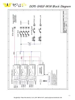
Page 59: ...61 Eagle Eye Power Solutions LLC 877 805 3377 www eepowersolutions com DCPS SHELF 9KW Block Diagram ...

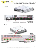
Page 60: ... Solutions LLC 877 805 3377 www eepowersolutions com DCPS SHELF 9KWRectifier Shelf Rear View DC OUTPUT SNMP V3 USB Ethernet AC INPUT Frame Ground M4 TEMP1 2 Temperature H W Alarm Debug GUI BATT CELL EXT Alarm Front View ...

Page 61: ...ect Current DCF DC Fail DCH DisCHarge DCOV DC Over Voltage DCUV DC Under Voltage DCV DC Voltage ENT ENTer EQ MODE EQualize Charge MODE EQ EQualize Charge ERR ERRor FF Fan Fail FL MODE FLoat Charge MODE FL FLoat Charge LCA Load Current Ampere LDA output LoaD Ampere LED Light Emitting Diode LVD Low VoltageDisconnect MANUAL FL MODE MANUAL FLoat Charge MODE MANUAL EQ MODE MANUAL Equalize Charge MODE M...

Reviews: