background image

From lab to production, 

providing a window into the process 

-12-

www.dynisco.com

Rev: n/a

P/N: n/a

ECO: n/a

3. Power Up Sequence

Following the power-up self-test and logo screen, the instrument normally enters Operation Mode, 

from which the user can select the instrument’s Main Menu (refer to the Screen Sequence list). The 

exceptions to this are the first power-up after purchase, when option modules have been changed 

or if an error is detected.

Setup Wizard

An easy Setup Wizard runs automatically at first ever power-up. Follow the Wizard to setup 

parameters required for typical applications (screens marked w in the Screen Sequence list). A 

partial Wizard also runs whenever option modules have been changed, this only shows 

parameters affected by the changes. The Wizard can also be run from the Main Menu. It exits to 

Operation Mode once completed.

Start-Up Errors

These messages indicate that a hardware or configuration an error has occurred.

Caution: Do not continue with the process until the issue is resolved.

Message Displayed   

Reason

Option Slot 

n

 Error   

Fault detected. Replace the module in slot 

n

Configuration Problem


Check all instrument parameters before using


For Service Contact   

Details of who to contact if a fault persists

4. Operation Mode

This mode is entered at power on, or accessed from the Main Menu. If required, all Operation Mode 

parameters can be made read only 

(see Display Configuration).

Note: Configuration must be completed before starting normal operations.

Normal Operation

Subsequent screens allow the display and selection/adjustment* alarm status and trends.

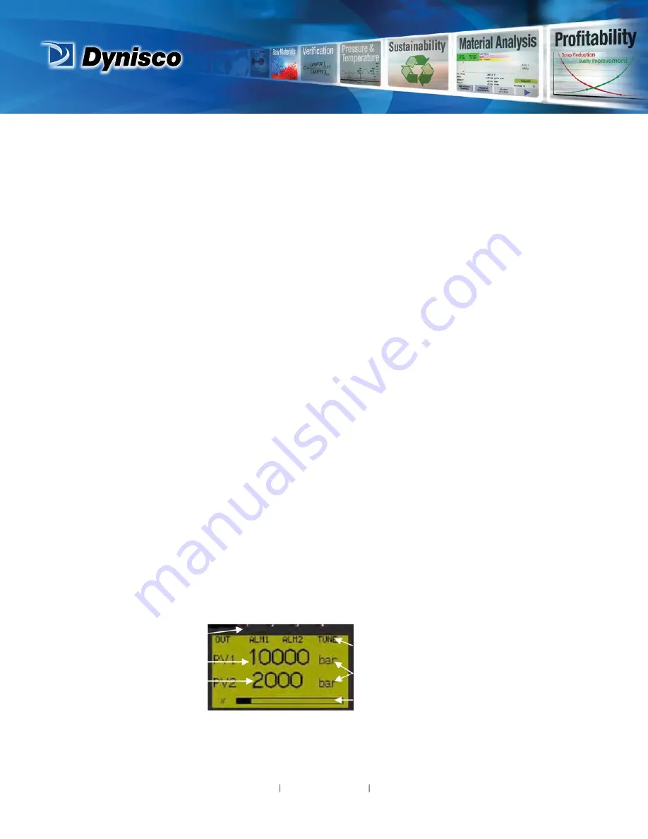
LED Indicators

LED Function Labels

Engineering Units

Input as Percentage of Span

Process Variable Value 1
Process Variable Value 2

Typical Operation Screen

Summary of Contents for ATC990

Page 1: ...From lab to production providing a window into the process 1 www dynisco com Rev n a P N n a ECO n a Dynisco ATC990 Graphical 1 4 DIN Process Controller Concise Product Manual Operating Manual...

Page 2: ...allation safety must be observed e g US National Electrical Code NEC and or Canadian Electrical Code Impairment of protection will occur if the product is used in a manner not specified by the manufac...

Page 3: ...ntings e Push the boards forward to ensure correct connection to the Display board f Replace the instrument by aligning the boards with the guides in the housing then slowly push the instrument back i...

Page 4: ...he instrument housing towards rear face of mounting panel until the tongues engage in ratchets and instrument is clamped in position Hold instrument firmly in position apply pressure to bezel only CAU...

Page 5: ...y marked All connections to the device must be made through a spade format or similar connection with connection to the spade terminal touching both the insulation and conductor material Use a standar...

Page 6: ...lution Impedance 10M resistive except DC mA 5 and V 47k Temp Stability Error 0 01 of span per C change in ambient temperature Supply Variation Supply voltage influence negligible within supply limits...

Page 7: ...to 2320 C 32 to 4208 F D 0 to 2315 C 32 to 4199 F E 240 to 1000 C 400 to 1832 F J 200 to 1200 C 328 to 2192 F K 240 to 1373 C 400 to 2503 F L 0 to 762 C 32 to 1402 F N 0 to 1399 C 32 to 2551 F PtRh 20...

Page 8: ...Scalable from 99999 to 100000 Decimal point selectable from 0 to 3 places but limited to 5 display digits e g 9999 9 Up to 15 scaling values can be defined anywhere between 0 1 and 100 of input Open c...

Page 9: ...e relay modules Remove the peg to fit dual relays all dual relay modules have reinforced isolation Single Relay Type Rating Single pole double throw SPDT 2A resistive at 120 240VAC Lifetime 500 000 op...

Page 10: ...8 data bits and 1 stop bit Odd even or no parity Isolation 240V reinforced safety isolation from all inputs and outputs Ethernet Connection Locates in Option Slot A Connection via RJ45 connector on to...

Page 11: ...cleaning Display Display Type 160 x 80 pixel monochrome graphic LCD with a dual colour red green backlight Display Area 66 54mm W x 37 42mm H Display Characters 0 to 9 a to z A to Z plus and _ Trend...

Page 12: ...n also be run from the Main Menu It exits to Operation Mode once completed Start Up Errors These messages indicate that a hardware or configuration an error has occurred Caution Do not continue with t...

Page 13: ...aved time At start of phase Delta reset timeout generator 4 5 saved time Err limit The process reaction goes into the wrong direction after setting the controller output pulse Err Parameter The estima...

Page 14: ...without DHCP Refer to the User guide from your supplier for help with communications 7 Strain Gauge Calibration Mode Press the to enter calibration mode from any location for quick access see Strain G...

Page 15: ...tune step is set too high it will create an overshoot and therefore needs to be reduced The pre tune step power is added to manual power and displayed to the user but is not changeable The expected ra...

Page 16: ...Max actual controller output Standby Active Limit The freezing of the output of the controller will last for a time specified by the Pressure stand by recovery time parameter If the parameter Pressure...

Page 17: ...ferential Input only applicable if Input2 card fitted and set to non temperature Primary Control Action Reverse or Direct acting Primary Secondary proportional band Integral Time Enter Value of requir...

Page 18: ...m through which the signal must pass before alarm deactivates Signal change Alarm n Min Minimum time the rate of PV change must be above the alarm threshold for a Rate Of Change Alarm to change state...

Page 19: ...e day of week used by the internal clock Recorder versions only Set Time w Sets the internal clock Time In hh mm ss Hours Minutes Seconds format Recorder versions only Display Configuration Enable Cus...

Page 20: ...t point values Alarm Status Active inactive status of all configured Alarms Trend View s A trend graph of PV1 PV2 or Differential or the Max Min value of the PV between samples Any active alarm s are...

Page 21: ...s pfl for profiles is added automatically Caution Existing files folders with the same name will be over written Writing Configuration File The file is being written Caution Do not disconnect USB devi...

Page 22: ...ations section for details Engineering Units w Select display units from C F K bar RH pH psi or none Decimal Point Position w Display resolution with 0 1 2 or 3 decimal places Temperature inputs are l...

Page 23: ...h you conduct the High end calibration and required offset for calibration Calibration reminder Calibration reminder Enable or Disable Calibration reminder Calibration Reminder Date Set the date that...

Reviews: