PEB-4720 Main Board
10
C
C
h
h
a
a
p
p
t
t
e
e
r
r
2
2
H
H
a
a
r
r
d
d
w
w
a
a
r
r
e
e
S
S
e
e
t
t
u
u
p
p
Model H700 Assembly
Please make sure that the system power is turned off and the power supply is disconnected when
making any hardware changes to Model H700.
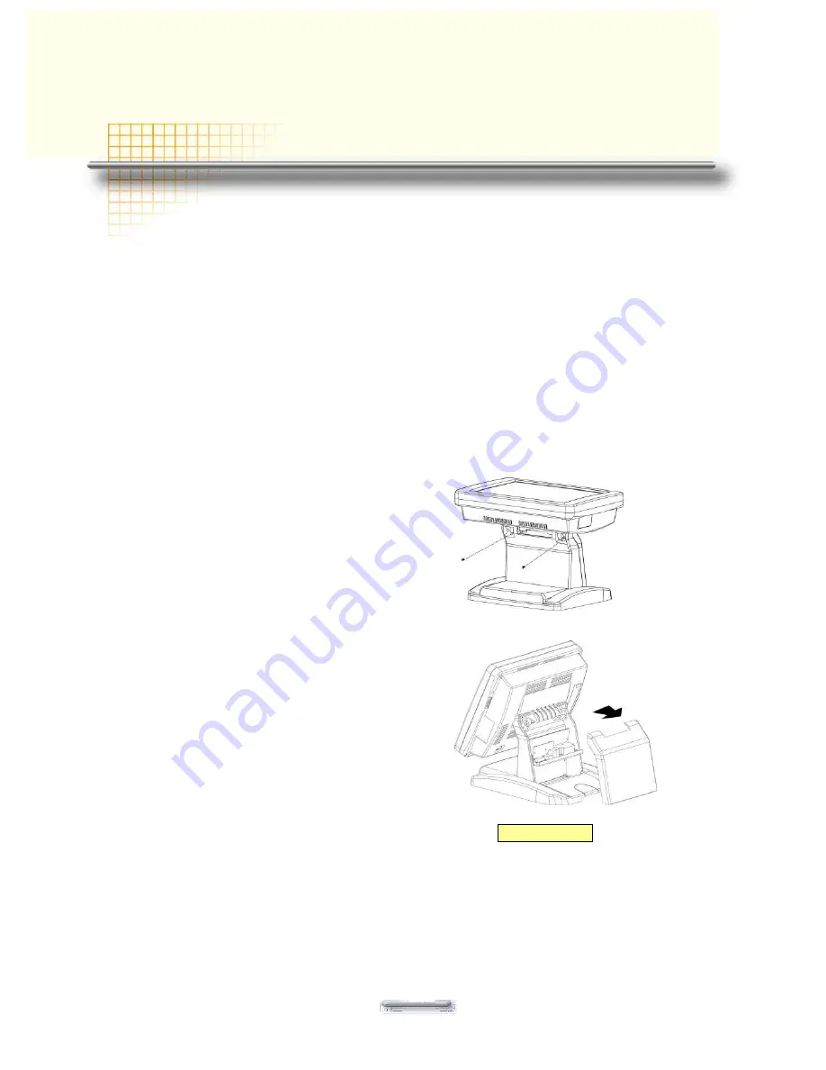
Remove the rear neck plate
There are two I/O ports, 9000PB0700 and 9000PB0710, located on the back of the neck. The
rear neck plate must therefore be removed before alterations can be made to the hardware. As
an example, to set up for DC+5V or DC+12V at Pin9 of COM1 or COM2 or COM5, follow the
steps:
1. Tilt the screen to 180 degrees.
2. Unscrew the 2 screws adjacent to the hinges.
3. Tilt the screen to 90 degrees.
4. Remove the rear neck plate.
5. Select the appropriate jumper settings as needed; refer to CON4&CON41 of Com1 and
COM2 D-sub connector and COM5 RJ-45 connector.


