MagTek I 1710 Apollo Court I Seal Beach, CA 90740 I Phone: (562) 546-6400 I Technical Support: (888) 624-8350
www.magtek.com
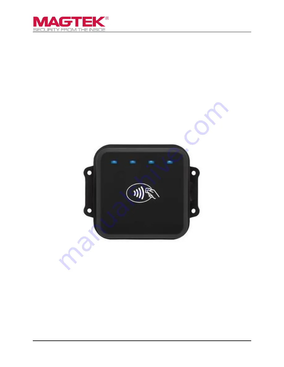
DynaWave
OEM Contactless NFC Module
Installation and Operation Manual
September 2018
Document Number:
D998200265-10
REGISTERED TO ISO 9001:2015


