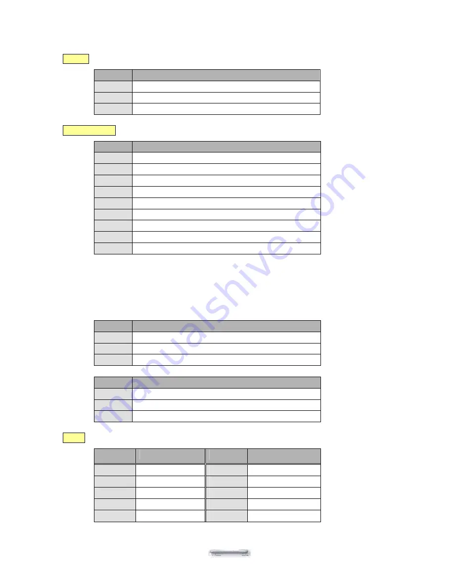
PEB-4720 Main Board
59
CON13
Audio line output EAR connector
PIN No.
DESCRIPTION
1
EAROUT-L
2
GND
3
EAROUT-R
CON4&CON41
RS232 port COM1 and COM2 D-SUB connector
PIN No.
Description
1
DCD
2
SIN (Rx)
3
SOUT (Tx)
4
DTR
5
GND
6
DSR
7
RTS
8
CTS
9
RI/DC output (RI is the default setting)
Pin9 signal can be selected as standard RI or DC power output depending on the JP2 and JP3
jumper settings. The default settings are for RI.
Attention: For devices using external power supplies and connected through Pin9 of COM1 or COM2, JP2
and JP3 should be open.
JP3
Description
1-2
PIN9 of COM1=DC +12V
3-4
PIN9 of COM1=RI (Default setting)
5-6
PIN9 of COM1=DC +5V
JP2
Description
1-2
PIN9 of COM2=DC +12V
3-4
PIN9 of COM1=RI(Default setting)
5-6
PIN9 of COM2=DC +5V
CON1
I/O Bus connector
PIN No.
Description
PIN No.
Description
1
EAROUT_L
2
DIO_IN00
3
DIO_OUT01
4
DIO_OUT00
5
COM4_DTR
6
COM4_DSR
7
COM4_RTS
8
COM4_CTS
9
EAROUT_R
10
COM4_SOUT


