EN
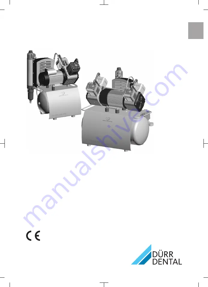
Primo, Duo, Trio, Quattro, DuoTandem, Quattro Tandem
Installation and operating instructions
0297
5152100003L02
*5152100003L02*
1910V001
Page 1: ...EN Primo Duo Trio Quattro Duo Tandem Quattro Tandem Installation and operating instructions 0297 5152100003L02 5152100003L02 1910V001 ...
Page 2: ......
Page 3: ... 23 Assembly 6 Requirements 24 6 1 Installation setup room 24 6 2 Setup 24 6 3 Information about electrical con nections 24 7 Transport 25 8 Quattro Tandem assembly and instal lation 25 9 Installation 26 9 1 Remove the transport locks 26 9 2 Establishing the compressed air connection 26 9 3 Pressure reducer 26 9 4 Place a collector tray underneath 26 9 5 Electrical connections 27 10 Commissioning ...
Page 4: ...placing the air intake filter 37 14 3 Replacing the filter of the mem brane drying unit 37 15 Taking out of use 38 15 1 Taking the unit out of use 38 15 2 Storage of the unit 38 Troubleshooting 16 Tips for operators and service techni cians 39 Appendix 17 Handover record 41 Contents 2 5152100003L02 1910V001 EN ...
Page 5: ...damage to machinery The following warning symbols are used General warning symbol Warning dangerous high voltage Warning hot surfaces Warning automatic start up of the unit The warnings are structured as follows SIGNAL WORD Description of the type and source of danger Here you will find the possible conse quences of ignoring the warning Follow these measures to avoid the danger The signal word dif...
Page 6: ...sema Soft tissue can be damaged as a result of careless handling Do not dwell in the area being treated for any longer than is necessary 2 1 Intended purpose The compressor is designed to supply com pressed air for dental applications 2 2 Intended use The air supplied by the compressor is suitable for driving dental tools The compressed air generated by the compres sor is delivered to the pipeline...
Page 7: ... specifi cally approved and authorized by Dürr Dental 2 6 Electrical safety Observe and comply with all the relevant elec trical safety regulations when working on the unit Replace any damaged cables or plugs immedi ately 2 7 Notification requirement of serious incidents The operator patient is required to report any serious incident that occurs in connection with the device to the manufacturer an...
Page 8: ...with EU Directive 2012 19 EU WEEE If you have any questions about the correct disposal of parts please contact your dental trade supplier An overview of the waste keys for Dürr Dental products can be found in the download area at www duerrdental com document no P007100155 Important information 6 5152100003L02 1910V001 EN ...
Page 9: ... with mem brane drying unit 4682 53 Fabric reinforced hose Hose nozzle Hose clamp Installation and operating instructions Appliance log book Collector tray with sterile filter 3 2 Optional items The following items can optionally be used with the unit these items do not bear the CE mark Pressure reducer 6040 992 00 Sterile filter 1640 981 00 3 3 Wear parts and replacement parts The following worki...
Page 10: ...pressure bar MPa 7 8 0 78 Cut off pressure max adjustable bar MPa 9 5 0 95 Safety valve maximum permissible oper ating pressure bar MPa 10 1 Pressure dew point at 7 bar 0 7 MPa C 5 Dimensions H x W x D cm 69 x 49 x 47 Weight kg 45 Noise level without sound insulation with sound insulation dB A dB A 65 49 66 50 Delivery without membrane drying unit at 20 C and 1013 mbar 0 1 MPa Value determined at ...
Page 11: ... Temperature C 10 to 55 Relative humidity max 95 Ambient conditions during operation Temperature C 10 to 40 Ideal temperature C 10 to 25 Relative humidity max 95 Classification Medical Device Class IIa Product description 5152100003L02 1910V001 9 EN ...
Page 12: ...ar 0 5 MPa l min 115 130 115 130 Pressure build up phase 0 7 5 bar 0 0 75 MPa approx s 80 70 80 70 Duty cycle 100 100 Start up pressure bar MPa 6 0 6 6 0 6 Cut off pressure bar MPa 7 8 0 78 7 8 0 78 Cut off pressure max adjustable bar MPa 9 5 0 95 9 5 0 95 Safety valve maximum permissible oper ating pressure bar MPa 10 1 10 1 Pressure dew point at 7 bar 0 7 MPa C 5 5 Dimensions H x W x D cm 69 x 4...
Page 13: ...t µm 35 Ambient conditions during storage and transport Temperature C 10 to 55 Relative humidity max 95 Ambient conditions during operation Temperature C 10 to 40 Ideal temperature C 10 to 25 Relative humidity max 95 Classification Medical Device Class IIa Product description 5152100003L02 1910V001 11 EN ...
Page 14: ...f pressure max adjustable bar MPa 9 5 0 95 Safety valve maximum permissible oper ating pressure bar MPa 10 1 Pressure dew point at 7 bar 0 7 MPa C 5 Dimensions H x W x D cm 69 x 49 x 47 Weight kg 50 Noise level without sound insulation with sound insulation dB A dB A 66 55 68 58 Delivery without membrane drying unit at 20 C and 1013 mbar 0 1 MPa Value determined at an ambient temperature of 40 C V...
Page 15: ...d transport Relative humidity max 95 Ambient conditions during operation Temperature C 10 to 40 Ideal temperature C 10 to 25 Relative humidity max 95 Classification Medical Device Class IIa Product description 5152100003L02 1910V001 13 EN ...
Page 16: ... 100 Start up pressure bar MPa 6 0 6 Cut off pressure bar MPa 7 8 0 78 Cut off pressure max adjustable bar MPa 9 5 0 95 Safety valve maximum permissible oper ating pressure bar MPa 10 1 Pressure dew point at 7 bar 0 7 MPa C 5 Dimensions H x W x D cm 76 x 74 x 52 Weight kg 80 Noise level without sound insulation with sound insulation dB A dB A 67 54 Delivery without membrane drying unit at 20 C and...
Page 17: ...ns during storage and transport Temperature C 10 to 55 Relative humidity max 95 Ambient conditions during operation Temperature C 10 to 40 Ideal temperature C 10 to 25 Relative humidity max 95 Classification Medical Device Class IIa Product description 5152100003L02 1910V001 15 EN ...
Page 18: ...ivery at 5 bar 0 5 MPa l min 220 255 Pressure build up phase 0 7 5 bar 0 0 75 MPa c s 100 90 Duty cycle 100 Start up pressure bar MPa 6 0 6 Cut off pressure bar MPa 7 8 0 78 Cut off pressure max adjustable bar MPa 9 5 0 95 Safety valve maximum permissible oper ating pressure bar MPa 10 1 Pressure dew point at 7 bar 0 7 MPa C 5 Dimensions H x W x D cm 76 x 74 x 52 Weight kg 85 Noise level without s...
Page 19: ...t µm 35 Ambient conditions during storage and transport Temperature C 10 to 55 Relative humidity max 95 Ambient conditions during operation Temperature C 10 to 40 Ideal temperature C 10 to 25 Relative humidity max 95 Classification Medical Device Class IIa Product description 5152100003L02 1910V001 17 EN ...
Page 20: ...0 5 MPa l min 225 260 225 260 Pressure build up phase 0 7 5 bar 0 0 75 MPa c s 100 90 100 90 Duty cycle 100 100 Start up pressure bar MPa 6 0 6 7 0 7 Cut off pressure bar MPa 7 8 0 78 9 0 9 Cut off pressure max adjustable bar MPa 9 5 0 95 9 5 0 95 Safety valve maximum permissible oper ating pressure bar MPa 10 1 10 1 Pressure dew point at 7 bar 0 7 MPa C 5 5 Dimensions H x W x D cm 76 x 79 x 52 76...
Page 21: ...Temperature C 10 to 55 Relative humidity max 95 Ambient conditions during operation Temperature C 10 to 40 Ideal temperature C 10 to 25 Relative humidity max 95 Classification Medical Device Class IIa Product description 5152100003L02 1910V001 19 EN ...
Page 22: ...40 515 440 515 Pressure build up phase 0 7 5 bar 0 0 75 MPa c s 90 80 90 80 Duty cycle 100 100 Start up pressure bar MPa 6 5 0 65 6 5 0 65 Cut off pressure bar MPa 8 5 0 85 8 5 0 85 Cut off pressure max adjustable bar MPa 9 5 0 95 9 5 0 95 Safety valve maximum permissible oper ating pressure bar MPa 10 1 10 1 Pressure dew point at 7 bar 0 7 MPa C 5 5 Dimensions H x W x D cm 76 x 102 x 62 76 x 102 ...
Page 23: ...Temperature C 10 to 55 Relative humidity max 95 Ambient conditions during operation Temperature C 10 to 40 Ideal temperature C 10 to 25 Relative humidity max 95 Classification Medical Device Class IIa Product description 5152100003L02 1910V001 21 EN ...
Page 24: ...nit The type plate of the compressor unit is located on the crankcase below the cylinder 1 1 Compressor unit type plate Membrane drying unit The type plate of the membrane drying unit is located on the side of the membrane drying unit 1 1 Membrane drying unit type plate 4 10 Evaluation of conformity This device has been subjected to conformity acceptance testing in accordance with the cur rent rel...
Page 25: ...re limiting valve 13 Humidity display 14 Fine or sterile filter 15 Rinsing nozzle 16 Membrane fibre 17 Sinter filter 18 Water collection chamber 19 Water outlet valve The compressor unit draws in atmospheric air and compresses it without oil It then transports the oil free compressed air to the membrane drying unit The cooler and the membrane dryer extract moisture from the compressed air The oil ...
Page 26: ...r the unit Install a fan for auxiliary ventilation in rooms where ambient temperatures exceed 40 C while the unit is in operation 40 C 6 2 Setup The following conditions must be taken into account for installation The air is filtered when it is sucked in This does not alter the composition of the air For this reason it is important to keep the sucked in air free of harmful substances e g do not su...
Page 27: ...tro Tandem assembly and installation For weight reasons the unit is not supplied fully assembled Instead the compressor units are installed at the site of use Set up the tank at the planned installation site Screw in the vibration dampers into the motor mounting Place the compressors on the vibration damp ers Attach the compressor units with the lock washers and nuts Insert the compressed air conn...
Page 28: ...ot included in the scope of delivery onto the pressure hose internal diameter 10 mm and secure it with a hose clip Connect the connecting sleeve of the pressure hose to the compressed air tube Fig 1 Duo with condensate separator 9 3 Pressure reducer Insert the pressure reducer into the quick release coupling Insert the pressure hose into the quick release coupling on the pressure reducer 9 4 Place...
Page 29: ...nect the mains plug to an earthed power outlet 10 Commissioning In many countries technical medical prod ucts and electrical devices are subject to regular checks at set intervals The owner must be instructed accordingly Turn on the unit power switch or the main sur gery switch Carry out an electrical safety check in accord ance with applicable local regulations e g the German Ordinance on the Ins...
Page 30: ...o the factory settings 1 2 1 On off switch 2 Pressure gauge 10 3 Checking the safety valve Correct operation of the safety valve must be checked when the unit is started up for the first time and again subsequently at regular intervals At the factory the safety valve is set to 10 bar 1 hPa checked and stamped DANGER Risk of explosion of the pressure tank and pressure hoses Do not change the safety...
Page 31: ...ted condensation water has been blown out 10 5 Adjusting the rate of flow at the pressure reducer The pressure reducer regulates the rate of flow in the system and adjusts it to the required operat ing pressure In order to adjust the rate of flow air needs to be extracted via a consumer Activate the air consumer unit Lift the rotary knob at the pressure reducer Adjust the rate of flow via the rota...
Page 32: ...essure gauge If the read off values differ from the factory set tings or if other settings are required the cut off pressure of the compressor can be adjusted at the adjusting screw on the pressure switch The start up pressure can then be adjusted using the pressure difference Δp Take off the pressure switch cover Adjust the cut off pressure P at the adjustment screw The cut off pressure increases...
Page 33: ...t the motor protection switch with the adjustment screw to the measured value observe the range between the MIN permissi ble setting and the MAX permissible setting of the motor protection switch see 4 Technical data Assembly 5152100003L02 1910V001 31 EN ...
Page 34: ...switch M1 Compressor unit M2 Fan motor membrane drying unit M3 Fan motor noise insulation if required 12 2 3 N PE AC 400 V layout X1 M1 M2 M3 Q1 1 3 5 2 4 6 1 1 P PE L1L2L3 PE N 3 I I I N X1 Mains connection 3 N PE AC 400 V Q1 Pressure switch M1 Compressor unit M2 Fan motor membrane drying unit M3 Fan motor noise insulation if required Assembly 32 5152100003L02 1910V001 EN ...
Page 35: ...PE PE PE 2 2 1 1 X1 X4 I I I I I I I I I I I I X5 Mains connection L N PE AC 230 V Q1 Pressure switch A1 Controller X1 Distributor rail X2 Plug connection of compressor unit X3 Plug connection of compressor unit X4 Distributor rail Q1 2 Motor protection switch Q1 3 Motor protection switch M1 Compressor unit M2 Compressor unit M5 Fan motor membrane drying unit Assembly 5152100003L02 1910V001 33 EN ...
Page 36: ...1 X5 X4 I I I I I I I I I I I I X1 Mains connection 3 N PE AC 230 V Q1 Pressure switch A1 Control box X2 Plug connection of compressor unit X3 Plug connection of compressor unit X4 Distributor rail X5 Distributor rail Q2 Motor protection switch Q3 Motor protection switch K1 Time lag relay M1 Compressor unit M2 Compressor unit M3 Fan motor membrane drying unit M4 Fan motor membrane drying unit Asse...
Page 37: ...he pressure switch by rotating it to the position I AUTO The compressor unit will start up automatically and fill the pressure tank When the cut off pressure is reached the compressor unit switches itself off automatically The unit can be switched off when required by turning the pressure switch to the 0 OFF set ting Usage 5152100003L02 1910V001 35 EN ...
Page 38: ...enance schedule Maintenance interval Maintenance work At regular intervals Empty the collector tray under the membrane drying unit the interval may vary depending on the ambient conditions and method of working empty it daily if the humidity is high Annually Replace the air intake filter in the compressor unit every six months if the concentration of dust is high Replace the fine or sterile filter...
Page 39: ...er 2 Air intake filter 14 3 Replacing the filter of the membrane drying unit Fine sterile filter Switch off the unit Disconnect all power from the device Unscrew and remove the filter cover Remove the fine sterile filter Insert the new fine sterile filter Replace the filter cover and close Sintered filter Unscrew and remove the filter housing Remove the sintered filter Insert a new sintered filter...
Page 40: ...lve Once the start up pressure has been reached the compressor will switch on With the compressor switched on and the con densate drain valve open wait until no more condensation water emerges Switch off the unit Close the condensate drain valve when no more air escapes Disconnect all power from the device Disconnect the compressed air connection on the quick release coupling 15 2 Storage of the u...
Page 41: ... of a unit piston is stuck motor pro tection has tripped Switch the unit off and dis connect it from the power supply remove the fan hood of the blocked compressor and rotate the fan wheel If this is not possible replace the piston and cylinder or the complete unit Humming noise from motor Motor capacitor is defective Replace the capacitor Compressor does not switch off Wrong size of compressor ai...
Page 42: ...Replace the air intake filter at least 1x per year The air intake filter must never be cleaned Defective membrane drying unit Replace the membrane drying unit Inform a Service Technician Water dripping from air con sumers Maintenance work not carried out regularly without membrane drying unit Regularly drain the condensa tion water from the pressure tank see 10 4 Draining the condensation water De...
Page 43: ...name Order number REF Serial number SN o Visual inspection of the packaging for any damage o Unpacking the medical device and checking for damage o Confirmation of the completeness of the delivery o Instruction in the proper handling and operation of the medical device based on the operating instructions Notes Name of person receiving instruction Signature Name and address of the qualified adviser...
Page 44: ......
Page 45: ......
Page 46: ......
Page 47: ......
Page 48: ...Hersteller Manufacturer DÜRR DENTAL SE Höpfigheimer Str 17 74321 Bietigheim Bissingen Germany Fon 49 7142 705 0 www duerrdental com info duerrdental com ...