CAPS (DSLS-DSLD)
TEE CAP (TC)
The Tee Cap provides access for cleaning and inspection. Usually on
horizontal runs, the Tee Cap is used to close the unused port of any Tee and
for clean out or access purposes only. When using clean-outs, always seal
the connection to prevent leaks.
The part list includes;
lx Cap with one Handle
lx smallerV-Band (BSI)
The next Items are for the Model DSLD only:
1x Outer Casing
1x Larger V-Band (BSI)
INSTALLATION PROCEDURES
STEP 1-
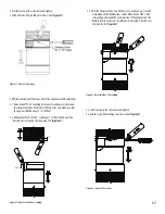
(only for horizontal installation): Add Viton® Caulking over the
Viton O-ring Gasket. See
Figure 40a.
Step 2
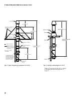
-Use the inner V-Band (BSI) to secure the inner Cap Kit to the flange
of the 90° Tee (T90, not included) as specified in the JOINT ASSEMBLY
section.
NOTE:
Be sure the handle of the Cap faces outward as shown.
See
Figure 40a or 40b
.
Figure 40b: Step 2 for installation of the TC
DRAIN TEE CAP (DTC)
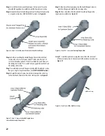
The Drain Tee Cap (DTC) is used as a drain forthe base of vertical
installations and must be connected to a suitable disposable point. It can
also be used as an access for clean outs or access purposes. (See
Figure 41
)
Same installation as a Tee Cap (TC).
ELBOWS (DSLS-DSLD)
ELBOWS (E2, El5, E30, E43, E45, E88, E90)
Elbows are used for changes in direction in horizontal or vertical
portions of a system. All elbows feature the standard joint assembly as
described in JOINT ASSEMBLY section. Elbows are used in combination to
make different angles ranging from 2° to 90° in horizontal and vertical
segments of the system.
Elbows are not designed to take bending loads and must be structurally
supported. Structural parts such as posts or beams may also be needed to
hold chimney supports in position. See ELBOW SUPPORT section.
Figure 42: 3, 15, 30, 45 and 90° Elbow
Figure 40a: Step 1 (only for Horizontal installation) Installation of the TC
Figure 41: Drain Tee Cap (DTC)
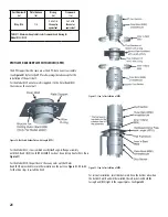
Step 3
- Mate the flange of the outer casing with the flange of the out
wall of the Tee section.
Step 4
- Secure with the bigger V-Band (BSI) by tightening the retaining
screw. See
Figure 40c.
Figure 40c: Step 3-4 for installation of the DSLD TC
25
Step 9
-Slide down the retaining band on the double flanged sleeve to
mate their flanges and tighten the retaining collar.
Step 10
-Then install the other V-band (BSI) over these flanges (like
regular joint assembly). See
Figure 38
.


