21
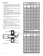
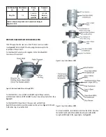
TABLE 14 - Expected number of tubes (11 oz) of Viton® per Joint Assembly
or of S-375 for exterior weathering
Inner Duct Diameter
Number of Tubes Per Joint
26
1/2
28
1/2
30
2/3
32
2/3
34
2/3
36
2/3
JOINT ASSEMBLY (DSLS-DSLD)
All components have a male and female end: the male end has a flue
extension and a black Viton® O-ring gasket (bottom side).
CAUTION:
Each section must have an O-ring on its male end. If not,
it may impair the sealing effectiveness. For any VERTICAL installation
(except for Variable Lenght (LV), no need for caulking when using the
O-ring. For any HORIZONTAL installation, add a bead of Viton® caulking
over the Viton O-ring to properly caulk.
NOTE:
Diameter of the DSLD shown in pictures for the installation
assembly are smaller then reality.
STEP 1:
Before installation, make sure there is a black Viton® O-ring on the flue
extension
STEP 2
(for
HORIZONTA
L installation only):
Only on Horizontal installation, add a bead of black Viton® caulking over the
Viton® O-ring.
NOTE:
Sealant Caulking is supplied by DuraVent and Individual tubes are
marked Fluorodyn Caulk VITON® code: VITON-S (2.5 oZ), VITON-L (11 oZ).
It must be ordered separately. See
Table 14
for number of tubes per joint.
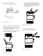
STEP 3:
For an easier installation, place the Inner V-Band (BSIK) on the spacers
below the flange of the first section. Join the two flanged ends of the duct
section together until it squeeze the Viton O-ring between both flanges.
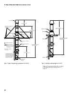
STEP 4:
Install the V-Band around the flanges making sure the flanges are located
within the V-Clamp.
NOTE:
Do not locate V-Band hardware at the bottom side of horizontal
duct joints.
STEP 5
:
Tighten the screws of the band with a screwdriver only (no screw gun).
NOTE:
Light tapping with a hammer all around the band while
tightening bolts helps align and pull flanges together.
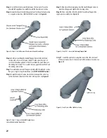
STEP 6
(for DSLD only):
Secure the Outer Casing with the Outer Band (BSE) and use a screwdriver to
tigten the screws (no screw gun).
Joint Assembly Step 1
Joint Assembly Step 2
Joint Assembly Step 3
Joint Assembly Step 4-5
Joint Assembly Step 6


