background image

13. Alarm relay

58

Dr. A. Kuntze 

I


Gutes Wasser mit System

Robert-Bosch-Str. 7a

40668 Meerbusch

+49 (0) 2150-7066-0 / Fax -60

www.kuntze.com

13.  Alarm relay

13.1.  Settings


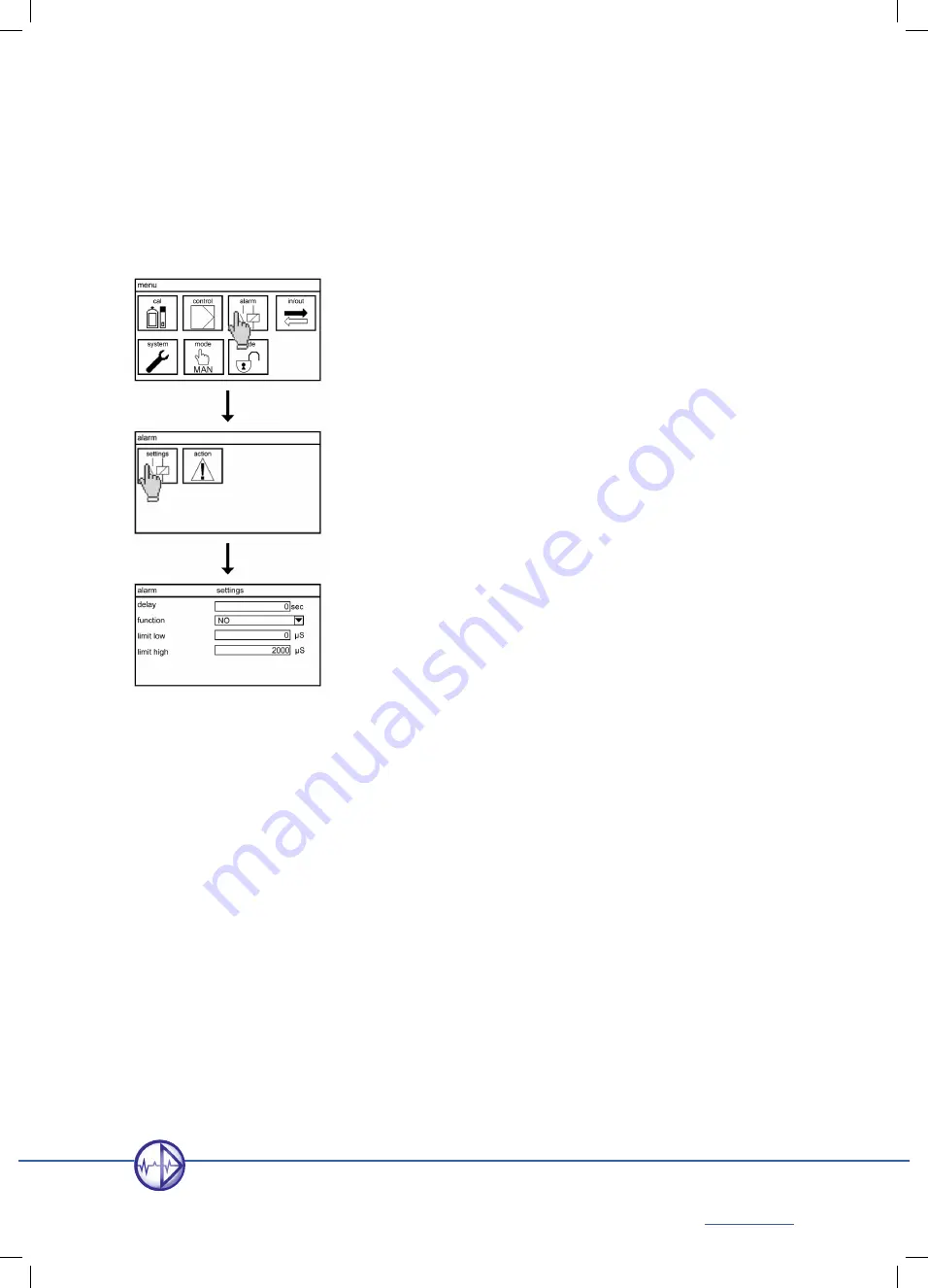
Select the symbol ALARM in the main menu.


In the submenu, select the symbol SETTINGS.


Here you can set the following parameters:

Delay

This defines a delay time – in case of an event, the alarm relay switches only after a specified interval. 

Display of the text message on the desktop and output of 22mA error current are not affected by this 

setting and will occur immediately.

Function

Here you can turn the normally open contact into a normally closed contact. That means that the relay 

is actively closed in case of normal operation and opens in case of alarm – with the advantage that 

power failure also leads to an alarm.

Lower limit / upper limit

You can define an upper and a lower limit. If the measured value is higher than the upper limit or lower 

than the lower limit, an alarm is issued via the alarm relay– if you have specified the limits as alarm 

 actions.

Summary of Contents for Neon Des

Page 1: ...Neon LF Dr A Kuntze Manual...

Page 2: ......

Page 3: ...tion and connections 14 2 1 Dimensions 14 2 2 Installation panel mounted housing 15 2 3 Installation wall mounted housing 16 2 4 Connections 17 2 4 1 Connection diagram 18 2 4 2 SD card 20 3 Operation...

Page 4: ...Memory 42 11 1 Store and load settings 42 11 1 1 How to save settings 43 11 1 2 How to load settings 44 11 2 Software update 45 11 3 How to save the diagnosis file 46 12 System functions 47 12 1 Lang...

Page 5: ...point configuration 83 17 1 1 ON OFF controller 84 17 1 2 P controller 84 17 1 3 PI controller 85 17 1 4 PID controller 85 17 1 5 3 point controller 86 17 2 S1 S2 CONFIG configurating the controller...

Page 6: ...19 2 4 Testing the safety features 99 19 2 5 Exchange of consumables 99 19 3 Restarting 100 19 4 Decommissioning and disposal 100 19 5 Facilitating functions 100 19 5 1 Store and load settings via SD...

Page 7: ...with some very convenient features The touch screen for example is the perfect complement to the graphical operation and gives you shortcut access to important menus from the main display The informa...

Page 8: ...oncerning safe operation shut it down and make sure it cannot be restarted You will notice that certain safety instructions are highlighted Warning highlights instructions for the protection of people...

Page 9: ...t industrial waste water process water disinfection and process control As a safety precaution measurement and calibration are checked for failure by the instrument Failures are indicated on the displ...

Page 10: ...20 00 mS cm c 1 00 cm 0 200 0 mS cm c 10 cm 0 2 000 mS cm 0 20 00 mS cm 0 200 0 mS cm 0 2000 mS cm 30 140 C Display Measured value and temperature with units Additional information selectable contact...

Page 11: ...after an adjustable interval Eventlog Stores up to 100 events Event help Provides help for current events Add on Functions can be added via code Add ons Digital input 2 For external controller stop lo...

Page 12: ...ncy or continuous controller 3 point controller Set points 2 set points with adjustable acting direction except 3 point controller Relays 2 potential free contacts 6A 250 V max 550 VA Hysteresis Adjus...

Page 13: ...Ansicht Installation panel mounted housing wall mounted housing Dimensions 138x138x83 mm 144x144x156 mm Weight 0 6 kg 1 0 kg Connections Cable inlet 2x M16 2x M12 optionally 2x M12 and 1x M25 Termina...

Page 14: ...9 0 2150 7066 0 Fax 60 www kuntze com 2 Instructions for installation and connections Attention Install the instrument in a place where it is not put under mechanical or chemical strain Note Mind the...

Page 15: ...Installation panel mounted housing Prepare an opening of 138 x 138 mm Clip the installation frame into the opening Place the instrument inside the frame and secure it with the M4 x 25 screws Tighten t...

Page 16: ...for as many cable glands as you wish to use and remove any remaining pieces from the openings Place the installation plate into the back frame and screw in the cable glands Drill two holes at 80 mm h...

Page 17: ...he screens on one side only The measurements are interference sensitive Use only our special cables with a very high insulation for short distances and for longer distances an impedance converter For...

Page 18: ...ctrode Inductive 1 4 1 voltage red 2 voltage black 3 measurement white screen 4 measurement green Pt 100 only for CM 7 9 10 7 T1 Pt 100 9 T2 Pt 100 10 RL for 3 wire connection cable Pt 1000 only for C...

Page 19: ...ad 500 Ohm Relay 1 70 71 Controller control variable set point1 Volume based dosing control variable set point 1 Max 2 A AC 250 V 550 VA DC 30 V 60 W Relay 2 73 74 Controller control variable set poin...

Page 20: ...d the SD card slot at the back of the housing Press the SD card with angled edge top right into the slot until it is into place By pressing the SD card the mounting is loose and the SD card will be ej...

Page 21: ...h factory settings the display shows at the top the instrument name and the time followed by the current measured value and the temperature In the bottom line the triangular symbol shows the way to th...

Page 22: ...he other direction 3 2 2 Submenus In submenus you will find on the left side the parameters and on the right side the corresponding settings The dark background indicates your current position in the...

Page 23: ...alues touching various areas of the screen gives access to different functions and submenus Touch text to switch to another desktop design time to enter the time setting menu event message to get sugg...

Page 24: ...by entering a value via keyboard or by selecting a setting from a drop down list or by activating or deactivating an item from an action list depending on the nature of the parameter Drop down lists...

Page 25: ...at are not activated in your instrument are crossed out and cannot be ticked Neon s support with the settings Parameters that do not fit to previous selections are hided e g in the TEMP menu correctio...

Page 26: ...rs abc key twice b appears OK key three times c appears abc key three times c appears Touch OK when the input is complete Now the instrument checks if the input is within the allowed limits If it is t...

Page 27: ...of output parameters for set point 1 Settings of control parameters for set point 2 Settings of output parameters for set point 2 De activating of relay and setting of acting direction Settings of del...

Page 28: ...uring input Settings for temperature measurement and compensation Selection of event text and contact for digital input 1 Selection of event text and contact for digital input 2 Settings for analog ou...

Page 29: ...dditionally the calibration Setting of contact data Help with active event messages Device information eventlog list of settings and overview on in and outputs Restore to factory settings Activating o...

Page 30: ...o enter another code and the other to stop the controller When the code is set to 1612 to give full access to all functions the main menu shows all functions of the instrument In the entry level versi...

Page 31: ...file and view various settings Full access code 1612 On this level you can enter and change all functions and settings If the full access code is set the CODE symbol in the main menu shows an open lo...

Page 32: ...deactivated Limits deactivated Data log on HOLD mA outputs on HOLD Controller OFF Modbus RTU on HOLD Desktop display active Alarm relay active Test functions deactivated Limits active Data log active...

Page 33: ...tal dissolved solids and is consisten with the residual after complete water evaporation Measuring range IL 0 2 000 20 00 200 0 2000 mS cm CM 0 20 00 mOhm 0 2 000 20 00 200 0 S cm c 0 05 0 2000 S cm b...

Page 34: ...uring range g l ppb mg l ppm g l ppt 0 2 000 S cm 0 1000 0 1 000 0 20 00 S cm 0 10 00 0 200 0 S cm 0 100 0 0 2 000 mS cm 0 1000 0 1 000 0 20 00 mS cm 0 10 00 0 200 0 mS cm 0 100 0 TDS factor If you ch...

Page 35: ...d a Pt100 or Pt1000 if you have connected a Pt1000 Other temperature sensors cannot be used Note You can connect temperature sensors with 2 wire or 3 wire connection If you use 3 wire connection make...

Page 36: ...the manual value to the same value as the reference temperature and set mode to manual Note If the mode is auto the input for the manual value is hided Temperature compensation The temperature depend...

Page 37: ...r the TDS factor Additionally a Zeropoint calibration is possible to eliminate possible influences by e g cable Select the symbol CAL to enter the submenu calibration Here you find three symbols REFER...

Page 38: ...8 2 TDS calibration reference Select the symbol RUN to start the calibration If you use a solution with known TDS take care that the sensor is free hanging and a least the electrodes or for a metal s...

Page 39: ...e no humidity connection between the electrodes For plugable connection you can remove the cable from the sensor for zeropoint calibration In the CAL menu select ZEROPOINT With OK you execute the cali...

Page 40: ...s will appear for them Contact For both inputs you can define whether the input should work as a normally open NO or normally closed NC contact Event You can select one of three text messages that wil...

Page 41: ...tivated in your instrument In the entry level version this means only relay 3 Set the mode to manual Select the symbol TEST in the submenu IN OUT In the submenu TEST you can switch all available relay...

Page 42: ...activated 11 1 Store and load settings You can save all settings on the SD card for safekeeping or to duplicate the settings into another instrument of the same type This way you can easily restore y...

Page 43: ...gs Make sure that an industry standard SD card max 2 GB with free storage space is plugged into the instrument In the menu IN OUT MEMORY select the symbol SAVE Select the symbol SETTINGS Acknowledge w...

Page 44: ...ect the symbol LOAD In the submenu select the symbol SETTINGS Acknowledge with OK The display shows the name of the file that will be loaded The name consists of the parameter and the date for example...

Page 45: ...es on an industrystandard SD card directly use no subfolder Plug the SD card into the instrument In the submenu MEMORY select the symbol LOAD Select the symbol SOFTWARE Acknowledge with OK The display...

Page 46: ...urrent values To collect all the information and maybe have it ready for a contact person you can save a diagnosis file on the SD card In the submenu MEMORY select the symbol SAVE Select the symbol DI...

Page 47: ...e System settings can only be changed with the full access code 12 1 Language For the menu a variety of languages are available The entry level version contains English and German To change the langua...

Page 48: ...12 2 Time To set the internal clock select the symbol SYSTEM in the main menu and in the submenu the symbol TIME When you select the field of either time or date a keyboard appears to enter the desire...

Page 49: ...display are found in the submenu SYSTEM DISPLAY If you have a touch screen instrument the touch screen calibration is also found in this submenu 12 3 1 Settings Contrast With CONTRAST you can adjust t...

Page 50: ...des Ger tenamens oben links wechseln Nach Betreten und Verlassen von Men s wird jedoch der Bildschirm angezeigt der in der Auswahlliste im Men angew hlt ist Selection If you select the line the deskto...

Page 51: ...d dosing This adds the calculated flow rate the controller output in and the status of relay 2 Autolock The autolock function ensures that an invalid code is set after an adjustable interval without o...

Page 52: ...ere you can enter an identification or location which will be shown on the left side of the top line of the desktop 12 3 2 Touch Cal for instruments with touch screen To calibrate the touch screen sel...

Page 53: ...2 Step 3 Step 4 Step 5 Note The touch screen calibration can also be started by touching the screen for more than 30 seconds 12 4 Contact In the submenu SYSTEM CONTACT you can store contact data of yo...

Page 54: ...ubmenu SYSTEM EVENT provides information on the event and suggestions how to solve it Select in the submenu SYSTEM the symbol EVENT With touch screen instruments you can reach this submenu directly by...

Page 55: ...erating hours of the instrument Eventlog The event log stores up to 100 events with the time they appear or leave Settings This submenu shows a complete list of all settings Press UP and DOWN to view...

Page 56: ...actory settings except the time date and contact Activated add ons will remain activated of course Select the symbol SYSTEM in the main menu and in the submenu the symbol RESET Go DOWN as indicated Ac...

Page 57: ...controller or volume based dosing Modbus RTU RS 485 needs additional hardware To activate add ons select the symbol SYSTEM in the main menu and in the submenu the symbol ADD ON A keyboard appears to...

Page 58: ...he text message on the desktop and output of 22mA error current are not affected by this setting and will occur immediately Function Here you can turn the normally open contact into a normally closed...

Page 59: ...ons as alarm actions If a box is marked with a tick the action or event will cause the alarm relay to switch An empty box means that the action or event does not cause the alarm relay to switch Overra...

Page 60: ...en activated Select the symbol IN OUT in the main menu and in the submenu the symbol MEMORY If the datalog add on is activated four symbols appear In the menu LOG PARA you define which parameters you...

Page 61: ...removing the card Otherwise data loss might occur and an error message will appear Note Always use a card with sufficient storage space even with ring mode otherwise the logging will not start Interva...

Page 62: ...date and the time for example pH060812_1322 csv for pH or mV060812_1345 for ORP measurements Each file starts with the device name the instrument number and the software versions followed by the log...

Page 63: ...e Select either 0 20mA or 4 20mA from the drop down list Note While 4 20mA gives slightly less resolution it helps identifying cable breaks Assignment Select which parameter you want to read out via t...

Page 64: ...oth ends of a long bus connection should be terminated with termination resistors of 120 Ohm With Neon instruments you can activate the termination via menu Note Activate the bus termination only at t...

Page 65: ...25 0x7D Response Function code 1 Byte 0x03 Bytes 1 Byte 2 x N Register value N x 2 Bytes N quantity of registers Write single register Function code 1 Byte 0x06 Register 2 Bytes 0x0000 to 0xFFFF Write...

Page 66: ...ge of a given range In that case the value of the first register lies within 0 0 and 10000 100 The third register conatins a code indicating a unit or text refer to table units and texts Numerical val...

Page 67: ...in the second register remains a 2 Measured value and range limits have to be divided by 100 to achieve two decimal places Registers 4 and 5 show the range of the lower limit which is 2 00 16 00 and t...

Page 68: ...6184 3 u_8 1 Status relay 1 controller 6544 3 u_16 2 Status relay 2 controller 6568 3 u_16 2 Status relay 3 alarm relay 6592 3 u_16 2 16 3 3 Event messages and calibration results Up to 100 event mes...

Page 69: ...ar hour 202 u_16 2 first entry minute second 203 u_16 2 first entry code refer to the following table 204 u_16 2 second entry day month 205 u_16 2 100 entry code 600 u_16 2 Calibration log index first...

Page 70: ...ng input 35 Check temperature input 40 Out of measuring range below range 41 Out of measuring range above range 50 Zero point 51 Slope 60 No SD card for saving 61 No SD card 62 SD card write error 63...

Page 71: ...data Via the interface all information on the instrument is available including which add ons are activated read only Information on the measurement module and the add ons are coded as 32 bit refer to...

Page 72: ...oded as 32 Bit value as follows Bit number Option 10 Module pR 11 Module DES 12 Module CM 13 Module IL 14 Module Gas 15 Module Standard 16 3 5 How to read and write parameter settings Parameter regist...

Page 73: ...ngs and activated add ons Digital inputs 1 register Quantity Type Bytes Read write range Code 2096 8 u_32 4 no yes Operation mode 2240 3 u_8 1 yes no Settings for the measurement Parameter pR Buffer 1...

Page 74: ...surement 1408 12 string 24 yes no Input signal 4680 3 u_8 1 yes no Measuring range 4536 3 u_16 2 yes no Unit 4616 3 u_8 1 yes no Parameter Gas Measurement Analog 1 4464 3 u_16 2 yes no Slope Analog 1...

Page 75: ...6208 3 u_8 1 yes no Add on dig input 2 contact 6200 3 u_8 1 yes no System Language 2200 3 u_8 1 yes no Time 0 2 u_32 4 yes no Displaycontrast 2208 3 u_8 1 yes no Desktop design 2216 3 u_8 1 yes no Au...

Page 76: ...r 2128 indicates which add ons are activated as recently described Dependent on that some or all of the following parameters are available Name 1 register Quantity Type Bytes Read write Range Add on D...

Page 77: ...mA2 range min 6456 5 i_16 2 yes yes mA 2 range max 6464 5 i_16 2 yes yes Add on Modbus RTU Bus address 6608 5 u_16 2 no yes Bus termination 6640 3 u_8 1 yes no Add on controller Start delay 6680 5 u_1...

Page 78: ...RP 7400 Des Std LF 7496 5 i_16 2 yes yes S2 hysteresis 7008 ORP 7432 5 i_16 2 yes yes S2 p range 7016 ORP 7448 5 i_16 2 yes yes S2 integral time 7024 5 i_16 2 yes yes S2 differential time 7032 5 i_16...

Page 79: ...u_16 2 yes yes Pulse type 7320 3 u_8 1 yes no Pulse frequency 7336 5 u_16 2 yes yes Pulse pause 7344 5 u_16 2 yes yes Pulse min 7352 5 u_16 2 yes yes Rel 1 on off 6904 3 u_8 1 yes no Rel 2 on off 7184...

Page 80: ...determines which text applies starting with 0 3001 NO NC 3002 OFF ON 3003 pH mV 3004 Off low medium high 3005 Coax Triax 3006 PT100 PT1000 3007 Man auto 3008 No water level ext stopp 3009 4 20 mA 0 20...

Page 81: ...00 S 0 200 0 S 0 2000 S 0 2 000 mS 0 20 00 mS 0 200 0 mS 0 2000 mS 0 9999 ppt 0 9999 ppm 0 9999 ppb 16 3 7 Test functions To test the installation you can operate all relays and current outputs manua...

Page 82: ...NTROL In the CONTROL menu you find the following submenus S1 S2 CONTROL in which you can define the set point the controller type and its corresponding parameters S1 S2 CONFIG in which you define the...

Page 83: ...used since relay 2 is used for S1 In the menu CONTROL select the symbol S1 CONTROL Here you can set the following parameters Set point Define which value the measured value should reach Type Choose be...

Page 84: ...troller The P controller reduces the dosing when the difference between set point and measured value is smaller than the specified P range Within the p range the controller output is proportional to t...

Page 85: ...P controller then reduce the proportional range until the measured value fluctuates constantly around the set point Measure the time between subsequent maximum measured values The ideal P range is the...

Page 86: ...t controller Note Set point S2 cannot be used when S1 is configured as 3 point controller Note Relay 1 is assigned to OPEN and relay 2 to CLOSE The 3 point controller is used for actuators that have n...

Page 87: ...u have to assign the analog output to control variable S1 or S2 in the menu IN OUT mA OUT In that case you can shut off the relay completely in the menu CONTROL RELAYS In the menu CONTROL select the s...

Page 88: ...only for pulse type pulse pause For a pulse pause controller define as Pulse Pause time a time frame in which the relay is on pulse and off pause according to the control variable Note The pulse pause...

Page 89: ...he controller doses whenever the measured value is higher than the set point R1 R2 on off You can shut off the relays completely to prevent unnecessary wear and tear This is useful if you use the anal...

Page 90: ...e corresponding controller 17 5 Activating and deactivating the controller To activate or deactivate the controller you have to change the operation mode You can change the mode in the main menu by pr...

Page 91: ...eliable measured values are available Such situation occurs in case of the following events If the measuring input or the temperature input receives no signal no measured value available If a digital...

Page 92: ...ou can operate the circulation pump that provides water for the concentration measurement Note It needs a flow meter that turns the flow rate into digital pulses connected to the digital input 2 NPN m...

Page 93: ...llowing parameters Pump output Define how many liters per hour the pump feeds Pulses Define how many pulses the flow meter gives per liter This information allows the instrument to calculate and displ...

Page 94: ...iable S1 or S2 respectively see chapter analog output Warning If you invert the relay you must take precautions that the dosing is stopped in case of power interrupt If the instrument does not get pow...

Page 95: ...ct the symbol PUMP RELAY R2 on off If you do not want to control the circulation pump with the relay you can switch it off Relay 2 contact Relay 2 is a normally open contact In the menu you can invert...

Page 96: ...onnected actuators Manual operation of the relays and current outputs via the test function is not possible In the manual mode the controller is deactivated and you can operate the relays and current...

Page 97: ...uence on the controller Warning In the AUTO mode the controller actuates the dosing of possibly hazardous chemicals Check all connections feed lines and all settings before you activate the controller...

Page 98: ...testing of safety features and gaskets regular exchange of consumables Note Maintenance intervals depend on the application the installation the accuracy requirements etc Operation Interval suggestio...

Page 99: ...ing the level sensor out of the water Switching of the level sensor or loss of the flow signal has to lead to the text message low water or level or ext controller stop according to settings and to an...

Page 100: ...features the instrument provides such as the alarm relay the limits the dosage check and the controller stop 19 4 Decommissioning and disposal If you want to take the measurement out of service for a...

Page 101: ...not in a subdirectory Plug the SD card in the instruments slot and load the files via SYSTEM MEMORY LOAD SOFTWARE 19 5 3 Test menu During start up or in case of an alarm in your control center incons...

Page 102: ...e shooting If the problem remains it was probably not caused by the sensor If it has vanished the sensor needs to be replaced or at least cleaned and regenerated Conductivity cables Cables are among t...

Page 103: ...ng the raw signals of the sensors The later are invaluable for trouble shooting since they are not affected by any user settings such as calibration temperature compensation etc If for example you get...

Page 104: ...iagnosis file 20 7 Event help As an addition the instrument provides help for all events information on possible causes and suggestions for possible remedies These can be found in the menu SYSTEM EVEN...

Page 105: ...emperature it should be at approx 214kOhm Event message Cause Suggested remedies Out of measuring range Measured values exceed the measuring range Trend indication only If the measured value lies outs...

Page 106: ...be ignored by setting a delay time in the menu Alarm relay Event message Cause Suggested remedies Digital input 1 Low water Level Ext controller stop The digital input was closed by a connected senso...

Page 107: ...afety measure to shut down the controller in case of defective feed lines to prevent leaks of hazardous chemicals The instrument monitors the time of dosing with 100 controller output if you are using...

Page 108: ...te while the event message check measuring input ist displayed and the measured value shows this message appears Without valid measuring signal calibration is not possible Check the sensor connection...

Page 109: ...this pop up appears The allowed range covers all the usual settings Therefore the message is an indication that something is wrong with either the measurement or the reference value Popup message Caus...

Page 110: ...ops the logging when the SD card is full Change the SD card or remove some of its contents or select the mode RING to overwrite older data 20 9 Reset As a last resort it is sometimes necessary to rest...

Page 111: ...3 22 mA alarm 63 Autolock 31 51 Automatic mode 32 Averaging 33 B Bus address 64 Bus termination 64 C Calibration 39 info 39 touch screen 52 Calibration level code 31 Cell constant 33 Check measuring i...

Page 112: ...Disposal 100 Dosage check 107 E Eco mode 51 Event digital input 40 Event help 54 104 Eventlog 55 104 Event related support 54 104 F Facilitating functions 100 factor 34 Factory settings 56 Features 1...

Page 113: ...tion 64 communication parameters 65 read variables 66 register 66 Mode data log 61 Mode operation mode 32 98 Mode temperature compensation 35 N No appli 109 O Operating hours 55 Operation 21 via keys...

Page 114: ...e 45 101 Software version 55 System functions 47 T TDS 33 Technical Data 13 temperature compensation 36 Temperature compensation 35 reference temperature 35 Temperature measurement 35 correction 35 se...

Page 115: ......

Page 116: ...Robert Bosch Str 7a I D 40668 Meerbusch I Germany Fon 49 0 2157066 0 I Fax 49 0 21507066 60 info kuntze com I www kuntze com...

Reviews: