


5-5
2.
Turn superstructure so it is perpendicular to side frame to
be extended.
NOTE:
Do not attach cable on side frame step.
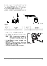
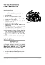
3.
Attach one end of cable (1, Figure 161) (6 x 19 normal Z to
ø14 – ø16 A type) on arm (2) and other end on side frame
(3). Connect it with an appropriate holding device on both
ends.
4.
Raise side frame (3, Figure 161) slightly with jack and
block (4). Extend arm (2) gradually to slide side frame out
until it hits stop.
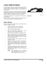
5.
After side frame (1, Figure 162) has slid into place, lower
superstructure to ground. Remove cable.
6.
Install ten spacers, harden washers and bolts (2, Figure
162).
NOTE:
Tighten bolts to 288 kg•m (2,083 ft lb).
NOTE:
Repeat procedure at other track frame support.
7.
After bolts for one side frame are fastened, repeat Steps
thru 6 for other side frame.
1
3
2
4
FG016366
Figure 161
2
1
FG016368
Figure 162
Summary of Contents for DX700LC
Page 2: ......
Page 72: ...OP001120 Safety 1 66 ...
Page 142: ...OP001121 Operating Controls 2 70 ...
Page 188: ...OP001122 Operation 3 46 ...
Page 197: ...OP001123 4 9 Inspection Maintenance and Adjustment ...
Page 282: ...OP001123 Inspection Maintenance and Adjustment 4 94 ...
Page 298: ...OP000030 Troubleshooting 6 6 ...
Page 301: ...OP001125 7 3 Specification ...
Page 308: ...OP001125 Specification 7 10 ...
Page 314: ...950106 00012E Index 8 6 ...


