


3-39
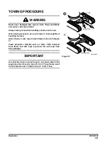
Rotating Pedal Valve (Optional)
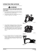
Attachment Rotating by Using the Pedal Valve
1.
Pressing end (1, Figure 86) is used to turn clockwise.
2.
Pressing end (2, Figure 86) is used to turn
counterclockwise.
NOTE:
Before activating the pedal, be sure to check
the function of the attachment.
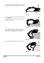
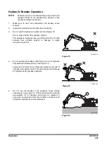
Locking the Pedal
When rotating is not needed, the pedal can be locked by using
the prop rod (3) locking device.
Locking is completed when the top end of the prop (3) is
positioned into pedal hole.
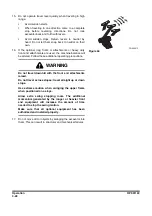
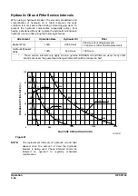
A.
Location for "UNLOCKING".
B,
Location for "LOCKING".
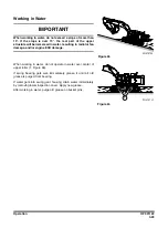
Attachment Rotation Using the Left-hand Work Lever
(Joystick)
For a machine equipped with an attachment that rotates,
rotation is activated while one of the control buttons is being
pressed on top of the left-hand work lever (joystick).
There are three buttons on top of the left-hand work lever. The
left and right ones are for controlling rotation.
NOTE:
The middle button is for the horn.
Left button is for counterclockwise rotation, and the right one is
for clockwise rotation.
FG000405
1
2
Figure 86
FG016191
1
2
Figure 87
FG000407
A
B
Figure 88
FG000035
Figure 89
LEFT-HAND WORK LEVER
(JOYSTICK)
Summary of Contents for DX700LC
Page 2: ......
Page 72: ...OP001120 Safety 1 66 ...
Page 142: ...OP001121 Operating Controls 2 70 ...
Page 188: ...OP001122 Operation 3 46 ...
Page 197: ...OP001123 4 9 Inspection Maintenance and Adjustment ...
Page 282: ...OP001123 Inspection Maintenance and Adjustment 4 94 ...
Page 298: ...OP000030 Troubleshooting 6 6 ...
Page 301: ...OP001125 7 3 Specification ...
Page 308: ...OP001125 Specification 7 10 ...
Page 314: ...950106 00012E Index 8 6 ...


