


5-4
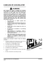
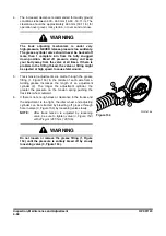
2.
Turn superstructure so it is perpendicular to side frame to
be retracted. Raise side frame to approximately a 15°
angle from ground using a jack. Side frame should slide by
its own weight and hit against stop.
NOTE:
If side frame does not slide in this condition,
allow side frame that is not contacting ground to
move back and forth slowly. See Figure 158.
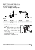
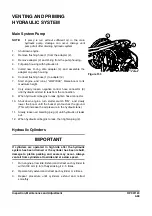
3.
After side frame (1, Figure 159) has slid into place, lower
superstructure to ground. Install five spacers, harden
washers and bolts (2).
NOTE:
Tighten bolts to 288 kg•m (2,083 ft lb).
NOTE:
Repeat procedure at other center frame
support.
4.
After bolts for one side frame are fastened, repeat Steps 1
thru 3 for other side frame.
5.
Store remaining bolts, spacers and washers with machine.
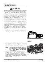
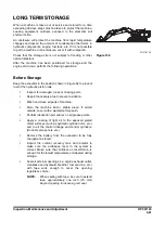
Frame Extension
1.
Remove five bolts, harden washers and spacers (1, Figure
160) from side frame (2) to be extended.
NOTE:
Do not loosen two bolts (3
Figure 160) on guide
(4).
NOTE:
Repeat procedure at other center frame support
(5
,
FG016363
15
90 ~ 110
Figure 158
CAUTION
The arm must be set at a 90 – 110° angle. Never set it
at an angle less than 90°
2
1
FG016364
Figure 159
2
5
1
4
3
FG016365
Figure 160
Reference
Number
Description
1
Bolt
2
Side Frame
3
Bolt
4
Guide
5
Center Frame Support
Summary of Contents for DX700LC
Page 2: ......
Page 72: ...OP001120 Safety 1 66 ...
Page 142: ...OP001121 Operating Controls 2 70 ...
Page 188: ...OP001122 Operation 3 46 ...
Page 197: ...OP001123 4 9 Inspection Maintenance and Adjustment ...
Page 282: ...OP001123 Inspection Maintenance and Adjustment 4 94 ...
Page 298: ...OP000030 Troubleshooting 6 6 ...
Page 301: ...OP001125 7 3 Specification ...
Page 308: ...OP001125 Specification 7 10 ...
Page 314: ...950106 00012E Index 8 6 ...


