background image


© Copyright 2003-2019 Dive Lab® Inc. All rights reserved. 

This Guide is made available for the express use of owners and users of the Dive Lab XLDS systems. 

This information is subject to periodic updates and changes.  Always check the Dive Lab web site for the latest versions. 

Document XLDS Guide – Section Four A 

Revised September 30, 2019


22

SECTION FOUR A: RDC REPAIR / MAINTENANCE / OVERHAUL 

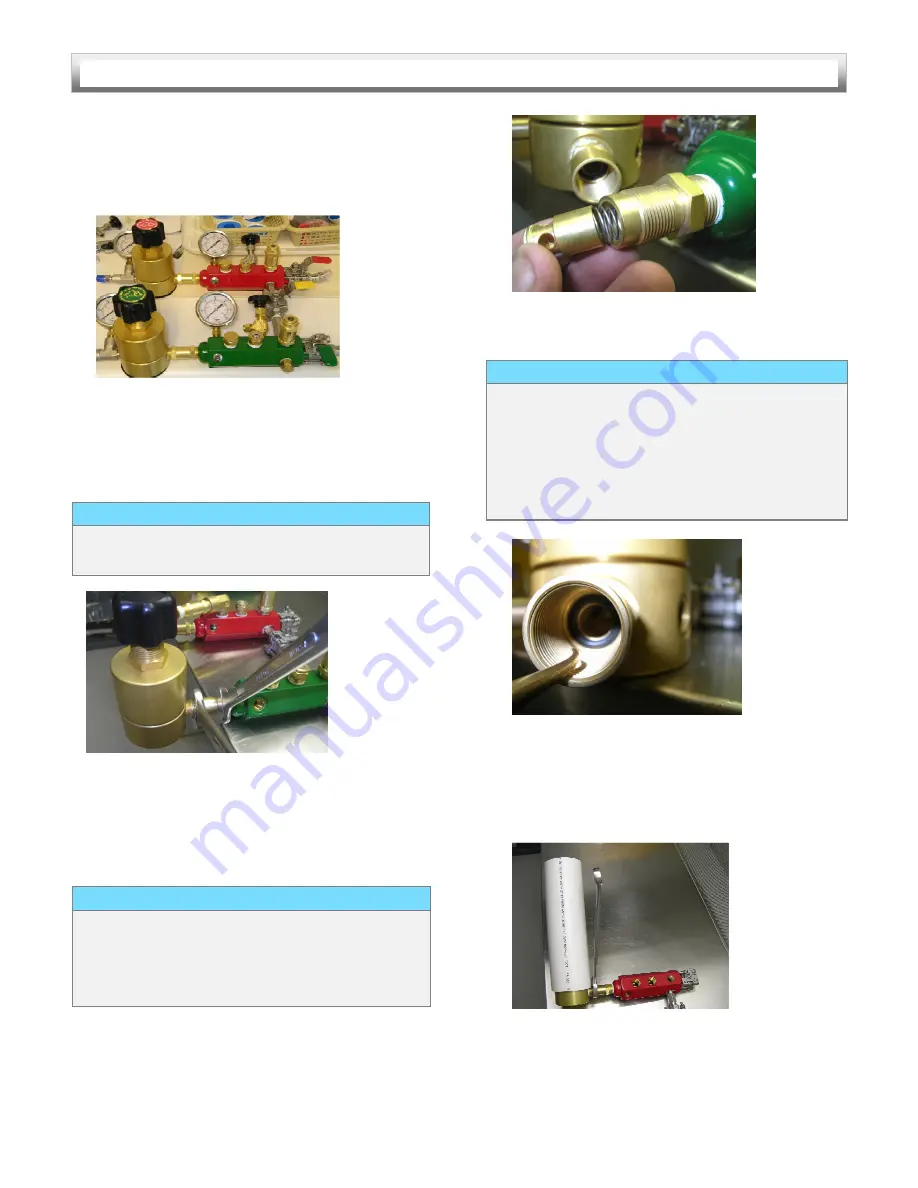
3.   Lift the complete two, or three diver manifold 
      assembly  from  the  box  as  an  assembly.  Place 

the manifold on a clean, flat, work table then 
remove the hand loader knobs.  


       Figure 32 


4.  Position the regulators, so they hang over the  
     edge  of  the  work  bench,  and  using  two  7/8” 

wrenches,  loosen  and  separate,  the  one-way 
valve, by turning counter - clockwise.  


    Figure 33


5.  Remove  the  spring  (3),  and  poppet/spring 

housing (2), then using the flashlight, carefully 
inspect  the  insides  of  each  half,  for  corrosion 
and contamination. 


        Figure 34


6.  Using the brass pick, remove the O-ring (5).


       Figure 35 

 
7.   Using 12” long piece of 3” diameter plastic 
      (PVC)  pipe,  hold  the  regulator,  while  turning 

the  check  valve  body counter-clockwise,  with 
the 7/8”wrench. 


       Figure 36


NOTICE 

Use  care  when  separating  the  valve,  so  the 
spring and poppet don’t fall free. 


NOTICE 

Remove the O-ring using a brass, or plastic pick 
only.  The  use  of  steel  picks  or  screw  drivers 
could  scratch  the  seat,  causing  the  valve  to 
leak. 


NOTICE 

If  the  body  (4),  spring  (3),  and  poppet/spring 
housing  (2),  are  clean  and  free  of  corrosion, 
cleaning  will  not  be  necessary,  and  simply 
lubricating  and  installing  the  new  O-ring,  is  all 
that  is  required.  Skip  steps  7  and  8  and 
continue to step 9. 


Summary of Contents for XLDS RDC-2

Page 1: ...on is subject to periodic updates and changes Always check the Dive Lab web site for the latest versions Document XLDS Guide Revised August 21 2019 EXTREME LIGHTWEIGHT DIVING SYSTEM RAPID DEPLOYMENT C...

Page 2: ...6 Ultra Light Umbilicals 7 Communication Strength Member 7 Pneumofathometer Hose 7 Grab Line 7 Diver Worn Harness and Manifold Compensating System 7 XLDS RDC 3 Specifications 8 Surface Supply Console...

Page 3: ...E AND OVERHAUL PROCEDURES continued Pages ICS Testing 40 System Flow Test 41 One way Valve Cleaning Overhaul 42 Cleaning Inspection of the ICS Manifold Block 43 Cleaning Inspection of the Dive Lab Int...

Page 4: ...rds Used in this User s Guide CAUTION This word indicates a potentially hazardous situation which if not avoided may result in minor or moderate injury It may also be used to alert against unsafe prac...

Page 5: ...em primarily intended and designed for use with Kirby Morgan Helmets and Full Face Masks but will also work with other demand mode equipment as outlined in the User Guide Definitions RDC 2 Rapid deplo...

Page 6: ...nd full face masks and diver worn systems that may be used with the XLDS and the specifications and limitations of use For conventional surface supplied air diving both the 2 and 3 diver RDC and HP su...

Page 7: ...pressure for the next inhalation cycle Breathing performance of the system allows breathing rates of up to 90 RMV to depths of 100 FSW and up to 75 RMV to depths of 132 FSW with most model KMDSI helm...

Page 8: ...htweight System must only be used with properly maintained and serviced Helmets Masks Emergency Gas Systems and support equipment as outlined in this User Guide DANGER Only persons properly trained in...

Page 9: ...apable of supplying at least 500 LPM Typical air supply sources include standard single or double SCUBA Cylinders Fire Fighting Cylinders and or any high pressure supply up to 4350 psig if DIN fitting...

Page 10: ...gauge calibration port and a main supply cross connect which allows intermediate air from either circuit to be lined up to the other divers reduced pressure circuit s Each diver s low pressure ALP su...

Page 11: ...he divers end the umbilical to ICS interface hose attaches to a 9 16 CGA O2 male fitting on the ICS one way valve Pneumo hook up Standard XLDS Umbilical 300 ft Communication Strength Member The commun...

Page 12: ...lbs Outer Dimensions Length 28 inches Width 27 inches Height 15 inches Number Diver Circuits 3 Red Green Yellow Max Depth Using 1 4 I D Umbilical one continuous length up to 330 long 165 fsw Maximum H...

Page 13: ...tached to a fully charged cylinder and only one cylinder supply should be on line at a time so that when the gas supply reaches approximately 400 psig it can be secured and the other supply opened By...

Page 14: ...to allow a normal ascent to the surface or to a place of safety where breathing gas can be restored The regulator used with the cylinder should be equipped with a relief bleed valve The bleed valve al...

Page 15: ...parts should be inspected for obvious contamination and re cleaned as necessary and carefully inspected for signs of wear and damage Drying All parts should be left to air dry in a clean controlled sp...

Page 16: ...sealing tape brush clean and inspect the threads for damage and then re tape and re make the joint Because this is often impractical to accomplish in the field minor leakage during system use can be...

Page 17: ...ly tape under tension starting one and a half 1 to two 2 threads back from the start of the threads Torque Tightening Pipe threads should be tightened using good engineering practice Tighten pipe thre...

Page 18: ...he regulator vent allow the inlet and outlet pressure to equalize by shutting off the inlet If leakage continues after the inlet and outlet equalize the vent seat 8 or piston seal 6 is leaking Replace...

Page 19: ...be removed from the system 3 Remove the regulator adjustment knob 15 and stem 16 as an assembly Figure 2 4 Apply several wraps of electrician s tape or equivalent around the upper housing 18 to preve...

Page 20: ...gure 8 9 Inspect regulator body for damage and or corrosion If nothing found install new kit 10 Install NEW high pressure valve assembly in regulator body Tighten to 80 100 inch lbs Figure 9 11 Instal...

Page 21: ...he stem 16 as well as the threads and secure into the top of the body Figure 16 8 The regulator should now be tested for proper operation Low Pressure Umbilical Supply Valves Cross Connect Valves Over...

Page 22: ...pneumo hose routing Tools and Components Needed 3 8 Open End Wrench 9 16 Open End Wrench 1 2 Open End Wrench Torque Wrench 0 250 inch lbs 3 8 Socket short 7 16 Socket 9 16 Socket 1 2 Socket Christo L...

Page 23: ...and remove the 4 bolts 9 and nuts 10 If the umbilical supply valves are being serviced remove the bolts and nut 25 Figure 22 7 Remove the center section 1 Figure 23 8 Press in on one side of the ball...

Page 24: ...the groove is centered with the stem then lightly lubricate the white plastic ball seals 6 and install with the concave sides in against the ball Ensure the plastic seals are properly seated Figure 28...

Page 25: ...s Flashlight 3 Diameter 12 Inch Long Piece of PVC Pipe used as a Regulator Holder 1 Tube Brush Preliminary To remove the valve from the manifold and regulator the complete manifold system must be unbo...

Page 26: ...valve by turning counter clockwise Figure 33 5 Remove the spring 3 and poppet spring housing 2 then using the flashlight carefully inspect the insides of each half for corrosion and contamination Fig...

Page 27: ...y tighten then install the regulator body hand tight 12 Install the PVC pipe over the regulator and using the 7 8 inch wrench loosen the two valve halves Tighten the regulator side of the valve until...

Page 28: ...amage corrosion and contamination If the valve is free of corrosion and damage wipe the threads of the stem 4 clean with a clean lint free cloth lightly lubricate the stem threads and packing area wit...

Page 29: ...t then load the regulator to 350 psig and check the discharge end at the female QD fitting for leaks by placing the open end of the QD in a glass of water for at least one minute to check for bubbles...

Page 30: ...roperly Figure 40 1 Sherwood Thermo Valves Exploded View Preliminary 1 Ensure the HP supply whips are disconnected from the cylinders and the system has been vented 2 Open both HP valves HP 1 HP 2 3 E...

Page 31: ...sh Corroded parts should be soaked in a 50 50 solution of vinegar and water for 1 3 hours then re clean thoroughly rinse and inspect for corrosion and damage If the body or stem shows any signs of dam...

Page 32: ...he HP block attach HP supply gas to the valve to be tested and slowly pressurize to the maximum HP supply pressure 4350 psig for DIN and 3500 psig for A Yokes At the same time spray the valve stem and...

Page 33: ...clean Tools and components needed 1 Open End Wrench 2 each 0 250 inch lbs Torque Wrench 5 16 Allen Wrench 1 16 Allen Wrench Needle Nose Pliers 10x Magnifying Glass Brass Pick Small Blade Pocket Knife...

Page 34: ...sary Pay particular attention to the seat area in the valve body Any nicks or dings in this area will cause valve leakage 7 Replace any components in question or the entire valve Reassembly 1 Lightly...

Page 35: ...nuary of 2011 the relief valves being installed in the XLDS RDC consoles is the Hylock Model RV2MF SS similar in operation and adjustment to the Circle Seal 0 400 psig adjustable brass body relief Thi...

Page 36: ...wrenches loosen the lock nut 2 and then remove the cap 1 Then drop out the spring 3 and spring disk 4 3 If the valve body is to be removed remove it at this time using the 13 16 wrench 4 Remove the bo...

Page 37: ...ring pressure to the manifold by rotating the regulator adjustment knob clockwise in until the LP gauge reads the desired relief pressure setting 4 Once the relief is set retest by slowly venting the...

Page 38: ...rade Silicon Grease Detergent Fresh water Basin or Sink Lint Free Cloths Lubrication XLDS components that require lubrication should be lubricated with Christo Lube Food grade silicone should be used...

Page 39: ...11 Pull the bottle adapter 24 free then using the pick carefully remove the upper and lower internal O rings 22 O ring 26 and O ring 21 12 Insert the 3 8 wooden or plastic dowel into port and push to...

Page 40: ...scratches do not remove easily it is best to replace the poppet After cleaning and inspecting components containerize to prevent contamination and set aside Figure 65 Poppet Cone Seat EGS Valve Clean...

Page 41: ...ICS regulator 1 Lay out all the new O rings for the ICS regulator and lightly lubricate them then lay them on a clean surface Use the ICS regulator exploded view drawing and this procedure for reinsta...

Page 42: ...O ring between the bottle adapter and the regulator body stays in the groove then torque to 150 inch lbs 7 Install the cylinder O ring 26 8 Install a new O ring 27 on the 20 port plug 28 install the p...

Page 43: ...d of the regulator body then press it in using the 3 8 wooden dowel Figure 69 Figure 69 7 Pack the piston assembly spring with Silicone grease Ensure the grease gets worked in around the coils so that...

Page 44: ...a helmet or mask or to FFM For the flow test the flow meter will be in place of the helmet of full face mask 1 Line up the RDC console with umbilical to one of the divers circuits ensuring that the H...

Page 45: ...bilical supply valve allowing flow through the flow meter Allow the flow to stabilize then take the reading at the widest point of the float 3 Record the following before flow starts Room temperature_...

Page 46: ...ion and brushing with a brass or stainless brush Re clean after using the vinegar solution then rinse thoroughly and inspect for signs of contamination corrosion and damage When finished air or blow d...

Page 47: ...e hose configuration for a full face mask green hose for helmets the center hose is the same 34 long 3 8 gates hose which is used on all XLDS systems To the right and left of the green hose is the BC...

Page 48: ...ance with XLDS cleaning procedure 7 Install new O rings on port plugs or hoses 3 8 24 small bore inflator hoses use a 010 O ring The center hose helmet full face mask hose and the O ring on the fittin...

Page 49: ...ouple times to check for a stable lock up pressure 5 Secure air at the RDC outlet then bleed down the umbilical to zero through the ICS EGS valve then secure the EGS valve and bring pressure back up a...

Page 50: ...g prior to start of flow 4 Record the following during flow HP pressure ______ psig LP discharge pressure ______ psig Flow ______ slpm If the flow is below 670 slpm contact Dive Lab Inc at 850 235 271...

Page 51: ...tenance required for the harness assembly Corrective maintenance is mainly repair replace the buoyancy bladder due to puncher repair replace power inflator To Remove Buoyancy Bladder Remove EGS cylind...

Page 52: ...Cover Figure 90 Power Inflator Inspect harness and back plate Figure 92 for signs of damage Because webbing is riveted in place it cannot be repaired by the user Contact Dive Lab if serviceability is...

Page 53: ...Document XLDS Guide Section Four A Revised September 30 2019 49 SECTION FOUR A RDC REPAIR MAINTENANCE OVERHAUL Figure 93 Maintenance for the Miller harness is simple Inspect for serviceability and da...

Page 54: ...o T s after the gauges are removed to help keep the Teflon tape and foreign particles from entering the system while using a brass pic and or 3 8 round nylon tube brush to remove old tape Cover all ex...

Page 55: ...est pressure of between 350 400 psig and held for 10 minutes zero leakage allowed as shown on the RDC HP and LP gauges Document the testing on the XLDS RAPID Deployment console Annual Pressure Joint T...

Page 56: ...position of the housing with the 5 16 Allen wrench tighten the cap 9 with the force of three fingers on the wrench or use a torque wrench and tighten to 40 50 inch lbs Note the final lift pressure 2b...

Page 57: ...ble for the express use of owners and users of the Dive Lab XLDS systems This information is subject to periodic updates and changes Always check the Dive Lab web site for the latest versions Document...

Page 58: ...L62 10 18 ICS Regulator 4XL62 9 11 ICS Regulator 4XL62 28 012 ICS Regulator 4XL62 25 008 ICS Regulator 4XL62 24 22 ICS Regulator 4XL62 7 010 ICS Regulator 4XL62 16 014 U70 Urathane ICS Regulator 4XL80...

Page 59: ...__________________________________________________________________ _______________________________________________________________________________ _____________________________________________________...

Reviews: