


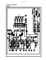


DINO 105T
67
ELECTRIC COMPONENTS
5336
→
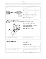
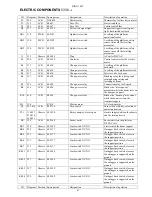
ID
Diagram Position Spare part no.
Designation
Description of operation
E1
224
LCB
DL8.058
Thermorelay
Thermorelay for the electric motor
F1
215
LCB
48.647
Fuse 10A
Start circuit fuse
F2
225
LCB
48.647
Fuse 10A
Control switch fuse
H3
237
LCB
48.2152
Yellow led signal light
Support outrigger circuit signal
light, limit switches closed
HG1 514
PLCB
48.2191
Quicksilver switch
Levelling of the platform,
operational sensor
HG2 520
PLCB 48.2192
Quicksilver
switch
Levelling of the platform, safety
sensor, turns off the levelling
movement
HG3 520
PLCB 48.2192
Quicksilver
switch
Levelling of the platform, safety
sensor, turns off the levelling
movement
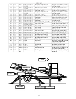
J1
111
Chassis 48.2085
Plug
AC outlet 230VAC
K1
224
LCB
48.2162
Contactor
Control contactor for the electric
motor
K3 517
LCB 48.650
Change-over
relay
Levelling of the platform
backward.
K4 514
LCB 48.650
Change-over
relay
Levelling of the platform forward.
K5
417
LCB
48.650
Change-over relay
Selector valve for boom
K6 327
UCB 48.650
Change-over
relay
Blocking relay for telescope and
turning during raising and
lowering of boom.
K7
525
LCB
48.650
Change-over relay
Connection relay for 2-speed
K8
616
LCB
48.650
Change-over relay
Blocks the "telescope out"
movement while the boom rests on
the transport support
K10 614
LCB 48.650
Change-over
relay
Blocks the "boom up" movement
while the boom rests on the
transport support
M1
134
47.816
Electric motor
AC electric motor
Q1
233, 414 LCB
48.2316
Turn switch
Turn switch with key, selection of
operating location
PL1 116,227,
233,414,
618,621
Chassis 48.3550
Rotary adaptor, electric part
electric supply between the chassis
and the turning device
PR
128
UCB
48.2145
Socket outlet
Socket outlet on the platform
230VAC 16A.
RK3 414
Chassis 48.3508
Limit switch NC/NO
Limit switch for boom support
RK4 232
Chassis 48.2177
Limit switch NC/NO
Outrigger limit switch, closes in
the support position
RK5 233
Chassis 48.2177
Limit switch NC/NO
Outrigger limit switch, closes in
the support position
RK6 233
Chassis 48.2177
Limit switch NC/NO
Outrigger limit switch, closes in
the support position
RK7 233
Chassis 48.2177
Limit switch NC/NO
Outrigger limit switch, closes in
the support position
RK11 227
Chassis 48.2248
Limit switch NC/NO
Outrigger limit switch, closes as
the outrigger is supported on the
ground
RK12 227
Chassis 48.2248
Limit switch NC/NO
Outrigger limit switch, closes as
the outrigger is supported on the
ground
RK13 227
Chassis 48.2248
Limit switch NC/NO
Outrigger limit switch, closes as
the outrigger is supported on the
ground
RK14 229
Chassis 48.2248
Limit switch NC/NO
Outrigger limit switch, closes as
the outrigger is supported on the
ground
ID
Diagram Position Spare part no.
Designation
Description of operation
Summary of Contents for DINO 105T
Page 2: ...DINO 105T 2...
Page 3: ...DINO 105T 3 OPERATING INSTRUCTIONS...
Page 4: ...DINO 105T 4 Valid from serial number 5336...
Page 8: ...DINO 105T 8 REACH DIAGRAM 120 kg...
Page 34: ...DINO 105T 34 LUBRICATION PLAN...
Page 37: ...DINO 105T 37...
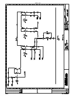
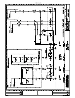
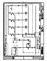
Page 69: ...DINO 105T 69 ELECTRIC DIAGRAM 5336...
Page 70: ...DINO 105T 70...
Page 71: ...DINO 105T 71...
Page 72: ...DINO 105T 72...
Page 73: ...DINO 105T 73...
Page 74: ...DINO 105T 74...
Page 75: ...DINO 105T 75 Notes...
Page 77: ...DINO 105T 77 HYDRAULIC DIAGRAM 5336...
Page 78: ...DINO 105T 78 Notes...