background image

40 


9.3


Primer Size Conversion  

9.3.1


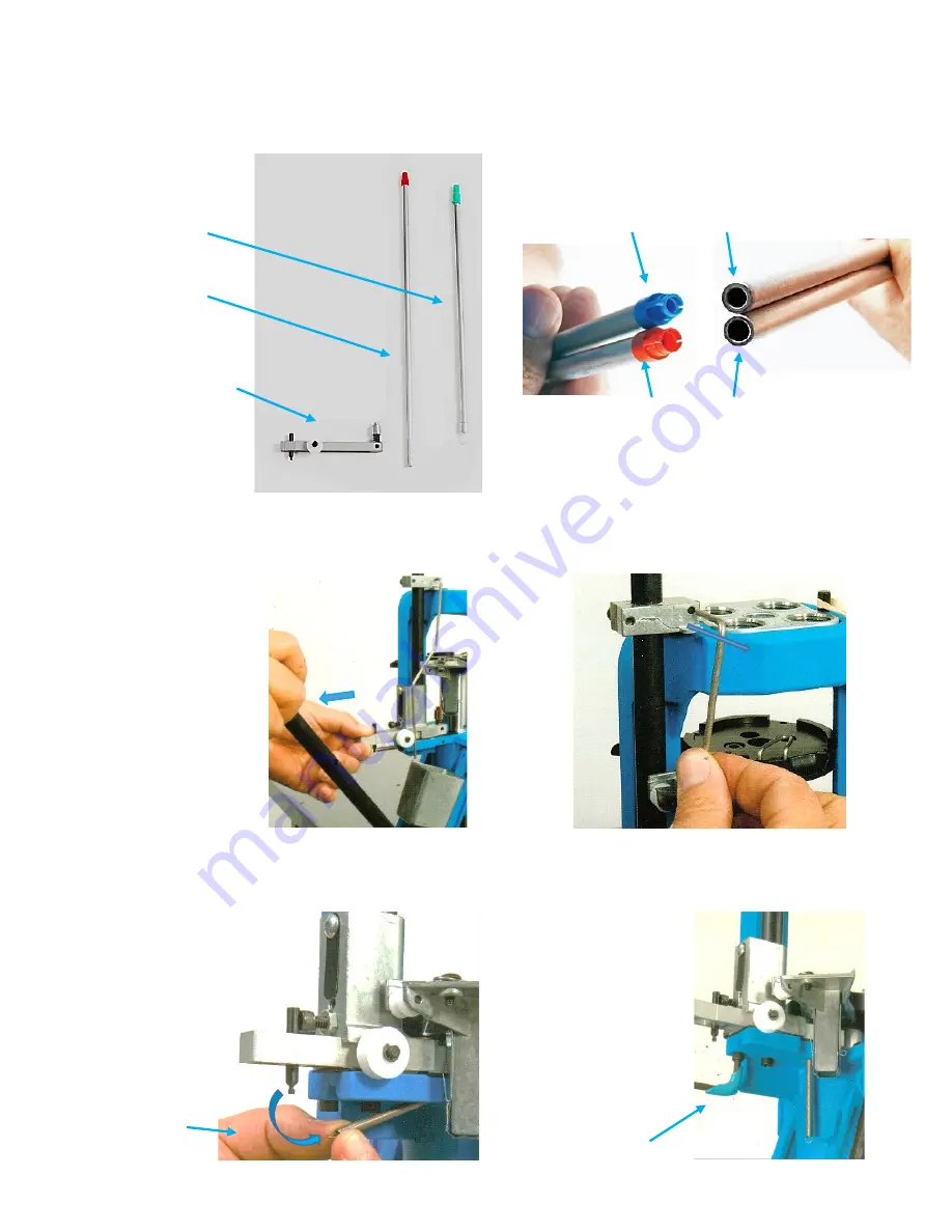
The RL550C comes configured for Small primers.  The Large Primer Components are shipped separately.   

9.3.2


The Magazine Tube Assembly uses color-coded plastic Primer Magazine Feed Tips.  The Large Primer Magazine Tip 
is red and Small Primer Magazine Tip is blue.  The Small and Large Aluminum Magazine Tubes have different inside 
diameters.  A conversion Kit for the large primer system is included in the original shipment “Tube Pack.” 

9.3.3


The Primer Size Conversion Kit included with the RL550C is shown below: 


9.3.4


To change Primer Size, remove the Operating Rod by lowering the Operating Handle partway down, pull back on 
the spring return Primer Slide, disengaging and removing the Operating Rod. 


9.3.5


Unhook the Primer Slide Return Spring from the Prime Slide.  Remove the two Primer Housing attachment Socket 
Head Screws with a 5/32” Allen wrench. 


Primer Size conversion Kit 


Large Primer 

Pickup Tube—

Green Tip 


Large Primer 

Magazine 

Tube/Orifice 

Tip—Red tip 


Large Primer Slide 

(Silver Cup) 


Remove Spring and 

let hang down 

Remove the two 

Primer Housing 

attachment screws 

Red Tip- Large Primer Magazine 


Blue Tip--Small Primer Magazine 


Summary of Contents for RL550C

Page 1: ...ersonal use only No part of this publication may be reproduced distributed or transmitted in any form or by any means including photocopying recording or other electronic or mechanical methods for commercial use without the prior written permission of Dillon Precision RL550C and Dillon RL550C Reloading System are trademarks of Dillon Precision Inc Rev B Oct 2021 ...

Page 2: ...ber Conversion 9 3 Primer Size Conversion 9 4 Powder Measure Conversion 10 ADJUSTMENT AND REPLACEMENT PROCEDURES Pagers 47 49 10 1 Shellplate Indexing Adjustment 10 2 Adjusting Primer Drop 10 3 Operating Rod Bracket Specification 11 TROUBLESHOOTING RL550C Pages 50 53 12 CLEANING AND LUBRICATING THE RL550C Pages 54 56 55 13 USING THE RL550C TO TRIM BRASS Pages 57 58 14 DILLON SUPER SWAGE 600 Page 5...

Page 3: ... or death Keep this manual in a safe location for future reference EXPLANATION OF SAFETY WARNINGS DANGER Danger indicates a hazard with a high level of risk that if not avoided will result in death or serious injury WARNING Warning indicates a hazard with a medium level of risk that if not avoided could result in death or serious injury CAUTION Caution indicates a hazard with a low level of risk t...

Page 4: ...o be used in the reloading process Again refer to established bullet and powder manufacturers Using the wrong powder or amount of powder or mixing powders can result in serious injury or death Never mix powders Always store the powder in its original container Never have more than one type of powder in the reloading area at one time preferably store powders in a separate room Observe all maximum l...

Page 5: ...r abnormal mechanical or environmental conditions or any unauthorized disassembly repair or modification This limited warranty shall not apply if i the product was not used in accordance with any accompanying instructions ii the product was not used for its intended function or iii the addition of any non authorized equipment 4 RL550C SHIPPING CONTENTS 4 1 Remove the following items from the top p...

Page 6: ...e the available Dillon Mounting Hardware Kit PN14355 Use small diameter washers on the top and large diameter washers on the bottom especially if using a wooden bench 1 RL550C with Toolhead Toolhead Retaining Pins and Primer System 2 Powder Measure with Powder Die 3 Operating Handle assembly with washer and lock nut 4 Bag containing Primer Early Warning System and Primer Follower Rod 5 Tube Pack a...

Page 7: ...et to your bench if you are NOT using the Dillon Strong Mount Allow about 1 8 clearance between the Platform and the Ejected Cartridge Chute Bin Bracket Fasten the Bracket to the bench with two self threading screws or bolts and nuts as shown below The Cartridge Collection Bin slides onto the bracket to catch completed cartridges Insert Handle in hole in Crank and thread Locknut on the Handle Tigh...

Page 8: ...ount PN22051 below Installation instructions are included with the Strong Mount The Dillon Strong Mount improves the stability of the system by distributing the loading forces over a larger area of the bench and provides mounting locations for optional bins and trays Standard Chute Bin Bracket can be mounted as shown Align cut out for Operating Handle clearance when Handle is pushed fully back ...

Page 9: ... Bracket as shown below by lightly greasing the short bent end and then inserting it in the hole Note the installed height of the Operating Rod Bracket is factory set 5 2 11 Hold the Operating Handle halfway down Pull the spring loaded Primer Slide out and position the Operating Rod so that it is aligned in the upper Small White Roller and the lower Large White Roller as shown below Cycle the Oper...

Page 10: ...re with the installation of the Shellplate Bolt 5 5 Carefully install the Index Ball Spring and Index Ball in the hole in the Platform as shown being careful not to drop the Spring or the Ball in the Shellplate Bolt Hole Place the Shellplate on the Platform number side up The Shellplate is in the available RL550C Caliber Conversion Kit Available RL550C Conversion Kit needs to be ordered separately...

Page 11: ...t screw will allow the Shellplate to rotate the Shellplate Bolt and stop the Shellplate from turning during normal operation 5 7 The RL550C uses caliber specific numbered Brass Locator Buttons as shown below The Locator Buttons retain the cartridge cases in the Shellplate during rotation They are easily taken out to remove cases from the Shellplate for checking reloading parameters The Buttons are...

Page 12: ...d Screws with a 5 32 Allen wrench Locate the caliber specific numbered Powder Funnel in the Caliber Conversion Box Drop the Powder Funnel with the grooved end up into the Powder Die Note the difference between Rifle and Pistol Powder Funnels below Powder Die with Lock Ring Loosen the two Powder Measure Clamp Screws with an Allen Wrench Place Powder Funnel in Powder Die RL550C Typical Rifle Convers...

Page 13: ...owder Measure down over the Powder Die and lightly tighten the two clamp screws 5 9 4 Install the bent end of the Powder Measure Failsafe Rod through the slot and hole in the Lock Link Assembly oriented as shown below Lock link Assembly Install upper end of the Failsafe Rod in the Lock Link Assembly Place Powder Measure on Powder die Lightly tighten the Powder Measure Clamp Screws Thread Power Die...

Page 14: ...etting the case mouth belling for pistol cases and the Powder Funnel to case contact on rifle cases described later 5 10 Note The RL550C ships with a Small Primer System installed Large Primer Components also are included with the RL550C for loading cartridges requiring large primers Refer to Section 9 3 on Primer Conversion Procedures and perform the primer size conversion now if required Tighten...

Page 15: ...Magazine Tube until you have read this entire manual 5 11 3 You can store the plastic Primer Follower Rod in the Magazine Tube when there are no primers in the tube by putting the Lever over the top of the Follower Rod to stop the alarm from sounding 5 12 Gently cycle the Operating Handle down and up again and push the Handle fully to the back to the priming position The Primer Slide should move s...

Page 16: ...r Warning Sensor PN16306 Roller Handle PN17950 Bullet Tray PN22214 Tool holder with Wrenches PN11541 Cartridge Case Bin and Bracket PN11185 RL550C Maintenance Kit PN97016 RL550C Toolhead Stand PN22055 RL550C Toolhead PN13909 and Powder Die PN20064 RL550C 750 Upgrade Kit PN35002 Strong Mount Bullet Tray and Roller Handle Package Deal ...

Page 17: ...ASE FEED AND SEAT PRIMER STATION 2 BELL CASE MOUTH PISTOL CASE DISPENSE POWDER STATION 3 PLACE AND SEAT BULLET STATION 4 CRIMP BULLET EJECT COMPLETED CARTRIDGE Toolhead Station 1 Toolhead Station 2 Toolhead Station 4 Toolhead Station 3 Shellplate Station 1 Shellplate Station 2 Shellplate Station 4 Shellplate Station 3 ...

Page 18: ... Dispense Powder The pistol case not the rifle case mouth is belled flared and powder dispensed into the case on the downstroke of the Operating Handle in Station 2 Case being pushed over the nose of the Power Funnel as it enters the Powder Die Station 1 Station 1 Primer Picked up from Primer Magazine by Primer Slide on Full Downstroke of the Handle and Seated on full push stoke of Operating Handl...

Page 19: ... cartridge The bullet is crimped on the downstroke of the Operating Handle in Station 4 and manually ejected by rotating the Index Sprocket completing the reloading cycle Crimping Bullet Station 3 Bullet Placement and Seating Completed cartridge ejected into Cartridge Bin by the Index Sprocket manually pushing the cartridge into the Ejector Wire Station 3 Station 4 Station 4 Eject Ejector Wire ...

Page 20: ...nd of the Locator 1 Spring Clip in until It just touches the rim of the brass case Back the Spring Clip up so that the end just clears the case rim by 015 020 Tighten the Adjustment Screw making sure that the back part loops of the Spring Clip is retained in the Locator Guides Verify that a case can be easily inserted into the Shellplate and removed without binding on the bent end If not adjust th...

Page 21: ...d case should drop freely in and out of the Pistol Case Gauge This Case Gauge can be used to gauge the completed reload as a final quality check 8 2 2 Rifle Size Die Adjustment For Bottleneck Cartridges Refer to Section 15 3 on headspace definition Note The Rifle Size Die and the integral Deprime Assemblies require separate adjustments Lower the Operating Handle Thread the Sizing Die down through ...

Page 22: ...wer step back the Die up and check another case Use a 7 8 wrench to hold the Die body and tighten the Die lock ring with a 1 Dillon Bench Wrench with the sized case in place Note Some Dies may require full contact slight cam over with the Shellplate Note Die Locking Procedure Always final tighten any Die Body i e Size Seat and Crimp Die Body Lock Rings with the appropriately processed case fully i...

Page 23: ...Operating Handle Refer to Section 16 4 on Primer Basics 8 3 1 Primer Magazine Feeding and Seating Components The RL550C incorporates an Automatic Linear Primer Feed System utilizing standard Dillon Primer Magazines and a Primer Shield along with a Large and Small Primer Slide The Black Plastic Primer Follower Rod is the Primer Early Warning System Low Primer Alarm Actuator and remaining primers in...

Page 24: ...istance to seating a primer can indicate an enlarged primer pocket that may not retain the primer Discard this case Verify that the system feeds primers as follows Remove the plastic Follower Rod from the Primer Magazine Tube Verify the Magazine Tube Size is correct The Magazine Tube with a Blue Tip is for small primers and the Magazine Tube with a Red Tip is for large primers Install the Magazine...

Page 25: ...le down and push the Operating Handle firmly to the rear push stroke seating the primer Remove the case and verify the primer is seated flush or slightly below flush Primer seating depth is an important parameter to control when reloading and can be a safety issue The ideal seating depth is 002 to 006 008 Max below the case head WARNING High or protruding primers can lead to slam fires in semi aut...

Page 26: ...round until all the primers are flat Pickup all the primers that are shiny side up by placing the Plastic Pickup Tip over the shiny side up primers in the Primer Flip Tray and gently pressing down Put the other half of the Flip Tray on the ribbed half with the primers that are anvil side up Hold the two halves together and turn them over Remove the top half of the tray and pick up the remaining pr...

Page 27: ...primers in a Primer Filler Tube Housing see below RF100 Voltages Small Primer Part No Large Primer Part No 120 VAC 97111 97077 220 VAC 97113 97112 Dillon RF 100 Automatic Primer Filler Dillon s RF 100 Automatic Primer Filler eliminates the task of manually filling primer pick up tubes Pour your primers from their box into the top of the RF100 Press the blue button In about two minutes the primers ...

Page 28: ...r dispensed The amount of powder that can be dispensed for each available bar is shown below 8 4 2 The RL550C is shipped with a Small Bar installed in the Powder Measure and a Large Powder Bar is shipped separately The Dillon Powder Measure uses Powder Bars that are specific to the range of powder dispensed as shown on the next page 8 4 3 Note The Powder Measure is only activated by a cartridge ca...

Page 29: ...ting Handle reaches the bottom of its stroke as indicated by the Charge Bar Arm just touching the Powder Body as shown below If the Charge Bar Arm has not traveled its full distance or tries to over travel raise the Operating Handle slightly while threading the 7 8 14 Powder Die up or down with your fingers while holding the Powder Measure from rotating Lightly tighten the Die Lock Ring and the tw...

Page 30: ...ie 8 4 7 Rifle Cases again full Powder Bar Travel is required as previously discussed Place an empty sized properly trimmed and expanded case in Station 2 with no powder in the Powder Measure It is highly recommended to always chamfer and deburr a rifle case neck to assist seating of the bullet and dropping powder Note the Rifle caliber specific Powder Funnel fits over the outside of the case neck...

Page 31: ...ent and write it down WARNING Put on safety glasses Remove the Powder Measure Hopper Lid and fill the Hopper with the prescribed powder and replace the Hopper Lid Label the Hopper with tape or a sticky note as to what powder is in the Hopper DANGER Never have more than one powder in the loading area Place a primed case in station 2 and cycle the Handle fully down Remove the case and dump the powde...

Page 32: ...ge overall length COAL Most loading manuals provide the COAL based on SAAMI Sporting Arms and Ammunition Manufacturers Institute standards The cartridge overall length specified in the reloading manuals for a cartridge is usually the minimum length for that bullet powder charge combination 8 5 1 The maximum cartridge overall length depends on the following factors The bullet must be seated deep en...

Page 33: ...AL If the bullet is not seated deep enough screw the Seating Die down 1 2 turn at a time As a guide one full turn moves the Die about 070 about the thickness of a nickel Replace the cartridge in Station 3 and repeat these steps until the correct overall length is achieved A quick method for pre setting the Die is to place a previously loaded good cartridge in the seating station and adjust the Die...

Page 34: ...a cartridge in the Die with the Handle down A quick method for pre setting the Die is to place a previously loaded good cartridge in Station 3 and adjust the Die down until just touches the case and adjust the Seating Stem down until it just touches the bullet Again check the COAL and adjust as necessary 8 6 Station 4 Bullet Crimping 8 6 1 Crimping is the final operation in the reloading process i...

Page 35: ...the revolver s cylinder to lock up after a few shots if a bullet is pulled far enough out of the case to contact the frame 8 6 6 Taper Crimping Pistol Cartridges A taper crimp flattens out the belling of the straight wall semi auto pistol case from the previous step Rimless straight walled or tapered cases such as the 9mm 40 S W and 45 ACP cartridges headspace on the case mouth and roll crimping w...

Page 36: ... screw the Die down 1 8 of a turn or less and lower the Handle Raise the Handle and inspect the cartridge If the belling of the case mouth is still present or more crimp is needed give the Die a 1 8 turn down or less and try again Continue making small adjustments until the desired amount of crimp is achieved again the crimp should reduce the case mouth diameter to no more than 001 002 Once the ad...

Page 37: ...2870 1 13930 20210 264 Winchester Mag 6 5 Rem B 13347 Y 12870 4 14047 20323 6 8 SPC R 13497 N 13014 2 14062 20142 270 Win 7x57 284 Win 1 13692 J 13456 1 13930 20122 270WSM 7mm WSM 7mm RSUM B 13347 7mm Short Mag 18416 6 15755 XL Powder Die 21253 Magnum Rifle Powder Bar 21353 20223 7 30 Waters 7 12501 N 13014 4 14047 20216 7mm Benchrest 1 13692 N 13014 1 13930 20142 7mm Brenneke 2 13692 J 13456 1 13...

Page 38: ...er System 97126 21665 378 Weatherby Magnum G 13313 378 Rifle 15010 7 13436 Belted Magnum Powder System 97126 20178 38 40 Winchester N 10004 W 913600 4 14047 20226 38 55 Winchester 375 Winchester 7 12501 V 13344 4 14047 20264 40 65 Winchester G 13313 40 Cal Rifle 11151 7 13436 20771 416 Remington Magnum 6 13347 RM 13415 4 14047 Belted Magnum Powder System 97126 20262 416 Rigby 404 Jeffries G 13313 ...

Page 39: ... screw will allow the Shellplate to rotate tighten the Shellplate Bolt and stop the Shellplate from indexing Make sure the Ejector Wire is not dragging on the Shellplate or any of the 4 legs on the Index Sprocket If it is dragging on the Shellplate adjust the Ejector Wire up If it is dragging on the Legs of the Index Sprocket verify that none of the 4 legs legs are bent if so straighten the legs g...

Page 40: ...r Size Conversion Kit included with the RL550C is shown below 9 3 4 To change Primer Size remove the Operating Rod by lowering the Operating Handle partway down pull back on the spring return Primer Slide disengaging and removing the Operating Rod 9 3 5 Unhook the Primer Slide Return Spring from the Prime Slide Remove the two Primer Housing attachment Socket Head Screws with a 5 32 Allen wrench Pr...

Page 41: ...Operating Handle all the way down Remove the Primer Side and store it in a safe place Note the position of the Primer Track Bearing yellow arrow Remove clean and replace the Track bearing including the area under the bearing This is a critical area to keep clean USE NO LUBRICANT 9 3 8 Remove the knurled Primer Shield Cap from the Primer Magazine Assembly and carefully pull the Magazine Tube straig...

Page 42: ...rm and place the Primer Seating Slide on the Track Bearing and align the Seating Punch Cup Assembly up into the Priming Depriming hole in the bottom of Station 1 in the Platform in the hole in the platform Slowly raise the Handle up to its rest position which lowers the Platform while wiggling the slide back and forth to center the Primer Cup in the Hole in the Platform Raise the Handle lowering t...

Page 43: ...a 7 32 Allen Wrench with the Operating Handle again held firmly fully back Overtightening these screws may damage the Primer Feed Body and or bind the Primer Slide 9 3 12 Replace the Operating Rod in the Operating Rod Bracket and position it between the Two White Rollers and reconnect the Primer Slide Return Spring 9 3 13 Perform a single primer feed test as previously described in Section 8 to ve...

Page 44: ...44 9 4 Powder Measure Conversion refer to the Exploded View below ...

Page 45: ...om the Powder Bar slot 9 4 3 To replace the Small or Extra Small Powder Bar remove the Spacer Bar Retainer Plug Store and slide the Spacer Bar and Powder Bar and Spacer out of the Powder Measure Slide the Powder Bar out of the Powder Measure by disengaging the White Cube from the Locklink Assembly Self locking Locknut on Pivot Screw Powder Bar Drive Slot Bell Crank White Cube Drive Pin Bell Crank ...

Page 46: ...lamp Screws Slide the top of the Failsafe Rod through the hole and slot in the Lock link assembly and snap the white Failsafe Bushing back into the Failsafe Rod Bracket on RL550C Retighten Self Locking Nut Pivot Screw just enough to remove any play and still allow free movement of the Powder Bar and Lock Link Assembly Slide the top of the Failsafe Rod into the Hole and Slot in the Powder Measure L...

Page 47: ...aising the Platform while moving the Platform side to side so that the end of the Alignment Fixture fits easily into the Priming Hole in the Platform Tighten the two Platform mounting screws Tighten both Platform Mounting Screws securely Verify that the Alignment Fixture fits into the priming hole freely by partially cycling the Operating Handle up and down Install the Shellplate and again make su...

Page 48: ...Feed body as shown below If not adjust the Primer Slide Stop on the back of the RL550C in or out no more than 1 8 of a turn at a time to fine tune the position of the Primer Slide See the graphical depiction below Reinstall the Primer Magazine Primer Cup must enter and be centered in the Hole in Platform and Shellplate without dragging Shine Flashlight here and look down Primer Shield Tube Flashli...

Page 49: ...et for the RL550C must be positioned at the height as shown below The Bracket must also be aligned rotationally with the base as shown Deviation from this dimension and alignment may cause primer feeding issues The position is set at Dillon and should not require adjustment Proper primer presentation Drop one primer in Magazine Shield Cap Operating Rod Bracket must be aligned and positioned as sho...

Page 50: ...one 5 One or more of the Index Sprocket Legs is bent down rubbing on the Ejector Wire Adjust Legs back flat 6 Make sure the Ejector wire is not dragging on the Shellplate Adjust Ejector Wire height to clear Shellplate and Ejector Wire Shellplate over traveling or jumping backward after indexing 1 Index Ball and Spring stuck down with gunk or debris or missing Remove Shellplate and clean top of Pla...

Page 51: ...specially the E clip on top of the Depriming Bolt Assembly The Priming Cup is not picking up primers reliably under the Primer Magazine in the Primer Feed Assembly Primers are being caught in Dispensing Tip 1 Remove the Primer Magazine from the Magazine Shield Caution Any primers left in the Primer Magazine will fall out Push a small cloth patch 3 8 x 3 8 wet with alcohol through the Magazine Tube...

Page 52: ... motion Slow down during the primer seating step be ready to stop if it is not seating smoothly or there is high primer seating resistance A stuck primer in Pickup or Magazine Tube 1 Throw the tube away Call Dillon for a new one High Primers Primers are not being seated flush or below flush with the bottom of the case 1 Shellplate loose To adjust loosen the brass tipped setscrew turn the Shellplat...

Page 53: ...t use sandpaper file or anything abrasive 2 Powder bar Small Bar Spacer or Measure Body galled from wear Return to Dillon for repair or replacement 3 Failsafe Rod Assembly missing or disconnected 4 Very fine grained spherical powder like Win 296 H110 and some Accurate Arms powder can get between the powder bar spacer and or the powder measure body and bind movement 5 Powder Bar Adjustment Bolt adj...

Page 54: ... lube such as Schaeffer High Performance Grease NLGI 229 High Moly Content or equivalent and Supreme 7000 Synthetic Plus 30W Motor Oil or equivalent 12 1 Lightly Oil Mainshaft every 5000 Cycles 12 2 Dillon offers an RL550C Series Machine Maintenance Kit PN 97016 that helps maintain the RL550C It includes RL550C Series Spare Parts Kit Compressed Air Pipe Cleaners Lubricating Grease Syringe Nylon Br...

Page 55: ...ns every 50 000 cycles Remove clean and lubricate the two Threaded Upper Link pins 10 Use a Socket or box end wrench to remove and replace the Threaded Upper Link Arm Pins Grease Zerk fitting 1 2 pumps while cycling Handle every 10 000 cycles Syringe Grease the Upper Link Arm Pins every 10 000 cycles both sides Remove Threaded Pins Clean and Grease ...

Page 56: ...ed 12 6 General Cleanliness The reloading process is inherently dirty because of residue from used primers leftover corn cobb from tumbling spilled powder and metal shavings from case trimming on the system The reloading process of sizing seating bullets and primers can generate metal particles Live primer residue along with leftover Case Lube are other contaminants that need to be cleaned up regu...

Page 57: ...ase with no expander ball to 90 utilizing the Dillon Rifle headspace gauge this means the case should stick up 020 above the top of the case gauge Station 2 Open Stations 3 Final headspace size and trim cases to proper length here utilizing Dillon Trim Motor and the Dillon Size Trim Die shown below in Station 3 This two step sizing operation provides a more repeatable and precisely sized case mini...

Page 58: ...0107 223 Rem 21765 303 British 19797 223 Rem Carbide 20106 308 Win 21364 220 Swift 62126 308 Win Carbide 20110 22 250 Rem 62140 300 BLK Carbide 20109 243 Win 62238 6 8 SPC 62290 6 5 Creedmoor 62237 7 62 x 39 21495 6 5x55mm 62231 RL550C Short Trim Die Toolhead 62164 RT1500 Trimmer Assembly Requires Short Trim Die Toolhead 62231 for making Blackout from 223 in one pass Deprime Station 1 Form size an...

Page 59: ...alled and could be crushed exploded if attempted 14 2 The available Dillon Super Swage 600 is an ideal companion to the RL550C for performing this operation after having deprimed and sized the crimped primer case in the RL550C Exchangeable Small and Large Adjustable Backup Rod i i Swaging Tip swaging primer pocket Exchangeable Small and Large Crimped Primer Pocket Swager Swaged Primer Pocket Crimp...

Page 60: ...60 15 RL550C EXPLODED VIEWS AND PARTS IDENTIFIER 15 1 Complete Assembly Exploded View 1 ...

Page 61: ...61 15 2 Frame and Lower Assembly Exploded View 2 ...

Page 62: ...62 15 3 Toolhead Assembly Exploded View 3 ...

Page 63: ...63 15 4 Platform and Components Exploded View 4 ...

Page 64: ...64 15 5 Primer Feed Assembly PN 20263 no Operating Rod Exploded View 5 ...

Page 65: ...65 15 6 Powder Measure Assembly ...

Page 66: ...66 15 7 Primer Early Warning System PN20302 Rod and PEWS Kit PN14497 PEWS Alone ...

Page 67: ...67 15 8 Primer Slide Assembly Small and Large Complete Assemblies PN14281 S PN14282 L Small 14281 Gold Cup Large 14282 Silver Cup ...

Page 68: ...at on their sides in a shallow box or cookie tray Pump three or four sprays on the cases and shake the box so the cases tumble and roll Repeat this process one more time making sure that the lubricant is distributed over the cases Let the cases dry for about 3 4 minutes before using them Over lubricating the brass can cause hydraulically formed lube dents during the resizing process This can also ...

Page 69: ...ridge headspace length is too short for the chamber too much front to back clearance the primer may not go off you may get poor accuracy stretched brass short brass life flattened primers or case head separation An example of stretched failing brass is shown below The brass flows towards the neck during the firing process and can cause the case wall to get thinner in a groove on the inside culmina...

Page 70: ...n general allows the reloaded cartridge to be fired in any firearm of the appropriate caliber Setting up the Sizing Die for a bottleneck case requires a higher level of precision than for straight walled cases Threading your Sizing Die down to the Shell Plate WILL NOT properly size bottleneck cartridges It is imperative to have a Head Space Case Gauge for the cartridge you are reloading A case gau...

Page 71: ...artridge case with a live primer Depriming a live primer is dangerous and can cause serious injury or death CAUTION Primers can leave a residue of primer dust behind especially if using a vibratory auto primer loader An accumulation of dust is a fire and an explosion hazard Keep the loading area and equipment free of any accumulated primer dust Use alcohol and paper towels to remove this residue W...

Page 72: ...entation It is important to keep records of the important parameters that were used in reloading the cartridge in a record book and labeling the cartridge storage container A quantity of 100 stick on labels with loading parameters is available from Dillion PN10446 see below Recording additional data such as the Date and the Powder Lot number is also recommended Dillon Reloading Stick On Label PN10...

Page 73: ..._________________________________________________________ __________________________________________________________________________________________ __________________________________________________________________________________________ __________________________________________________________________________________________ _____________________________________________________________________...

Page 74: ...___________ __________________________________________________________________________________________ __________________________________________________________________________________________ __________________________________________________________________________________________ __________________________________________________________________________________________ ________________________...

Page 75: ...75 18 RL550C TEMPLATE FOR DRILLING MOUNTING HOLES IN BENCH ...

Page 76: ...76 Dillon Precision Inc 8009 E Dillon s Way Scottsdale AZ 85260 480 948 8009 1 800 223 4570 FAX 480 998 2786 Website www dillonprecision com E mail dillon dillonprecision com ...

Reviews: