1-10 (No.HD001<Rev.001>)
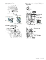
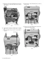
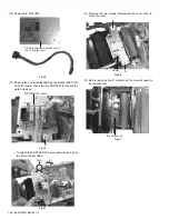
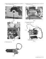
(7) Reattach the turn unit.
(8) Connect the wires from the turn unit following the picture
below.
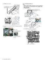
2.5.4 Attaching the MG unit
Note:
After mounting the MG unit, be sure to check the relevant
item referring to "2.6 Check details after mounting sepa-
rately sold parts".
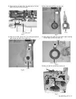
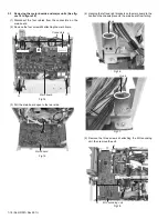
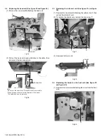
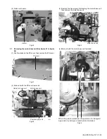
(1) Mount the MG unit.
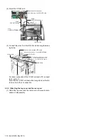
(2) Fix the MG unit with the three screws.
Screw : QYSDST3006NA
Bearing fitting hole
Make sure that the turn unit bearing
securely fits the hole on the main unit,
and the screw holes align.
Push the turn unit from the rear side to
attach the screw.
Turn unit
After attaching this screw, attach
another two screws.
Screw : QYSDST3006NA x 3
(Tighten the wire clamp
as shown in the picture
above.)
Wire clamp
CN1
Turn unit
Be careful to prevent wires from
touching nearby rotating objects
such as belts/gears.
(a)
(a)
MG Unit
(b)
(b)
(c)
(c)
(c)
(c)
Align the front end of the
MG unit to the grooves
(a) and (b) of the front
bracket.
While aligning the
grooves of the MG unit
bracket and the main unit
bracket, lower the back
end of the MG unit.
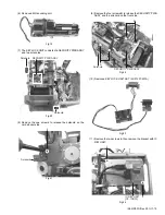
Make sure that the wires do not
run over the brackets.
If the wires run over the brackets,
release the wires.
Attention of there is
groove also under (a).
Screw : QYSDST3006NA x 2
Screw : QYSDST3006NA
MG unit
Summary of Contents for XID 8300
Page 1: ...No HD001 Rev 001 2010 10 SERVICE MANUAL CARD PRINTER XID8300 XID8300 DS XID8300C XID8300C DS ...
Page 46: ......
Page 56: ......


