


(No.HD001<Rev.001>)1-7
2.5
ATTACHING THE SEPARATELY SOLD PARTS
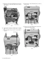
2.5.1 Preparation
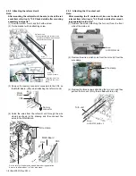
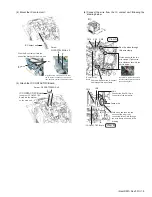
Before connecting the separately sold parts, remove the top cov-
er unit and the rear cover to pull open the MAIN Board.
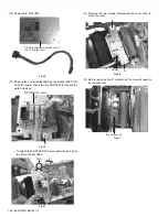
(1) Remove the two screws attaching from the rear side of the
main unit.
(2) Open the case cover,then remove the one screw.
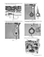
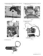
(3) Remove the top cover unit by sliding it to the direction of the
arrow.
(4) Remove the rear cover by pulling it open to the rear side.
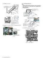
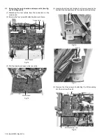
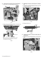
(5) Disconnect the wire connected to the MAIN Board.
(6) Remove the four screws attaching the brackets that fix the
MAIN Board.
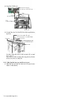
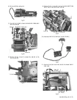
(7) Pull open the MAIN Board, and hook the two brackets at
the bottom of the MAIN Board to the frame of the main unit.
• Be careful not to catch wires in between.
Rear cover
Screw:
QYSDSP4012NA x 2
Top cover unit
Screw
Case cover
1
2
2
Slide the top cover unit
to the rear side about
10 mm, and then pull it up.
Top cover unit
Rear cover
Disconnect the connector from the turn unit.
(Only the models with turn unit)
Release the wires from the wire clamp.
MAIN Board
Screw : QYSDST3006 x 4
Main board
Summary of Contents for XID 8300
Page 1: ...No HD001 Rev 001 2010 10 SERVICE MANUAL CARD PRINTER XID8300 XID8300 DS XID8300C XID8300C DS ...
Page 46: ......
Page 56: ......


