background image

131 

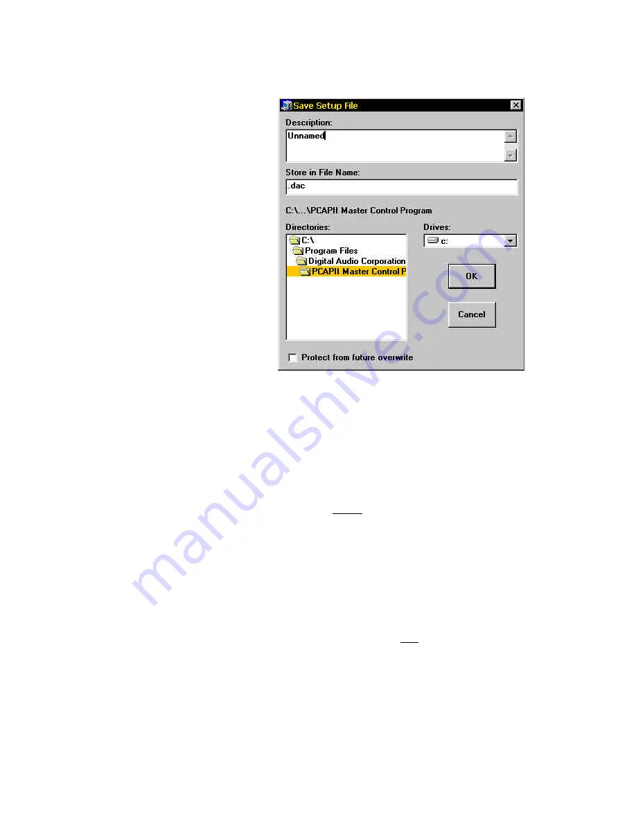
and type in any text desired.  It is recommended that 
the text be descriptive of the setup's application. 


Figure 4-61 Save Setup File Window 

 
4. 

You will need to specify a filename for the setup.  
Click on the 

Store in File Name

 text box, then type 

the desired filename (up to 256 characters).  All 
setup filenames 

must

 have the 

.DAC

 extension; 

thus, the 

.DAC

 extension is automatically included in 

the text box.  If you delete the 

.DAC

 extension, an 

error message will be generated. 

 
5. 

If you wish to protect your setup file from being 
accidentally overwritten in the future by the 

Save 

Setup File

 window, click the 

Protect from Future 

Overwrite

  box.  This does  not prevent deletion or 

overwrite by the Windows Explorer or by MS-DOS. 

 
6. 

Click on 

OK

 to save the setup file with the selected 

filename to the specified drive and directory.      


Summary of Contents for PCAP II

Page 1: ...PCAP II PERSONAL COMPUTER AUDIO PROCESSOR USER S MANUAL DIGITAL AUDIO CORPORATION A DRI COMPANY ...

Page 2: ......

Page 3: ...Manual November 2 1999 Version 12 0 DIGITAL AUDIO CORPORATION A DRI COMPANY 5121 Holly Ridge Drive Raleigh NC 27612 Phone 919 782 6767 Fax 919 782 6766 sales dacaudio com www dacaudio com Copyright 2000 by Digital Audio Corporation All rights reserved ...

Page 4: ......

Page 5: ...raining CD Recordings 31 4 PCAP II SOFTWARE REFERENCE MANUAL 33 4 1 Master Control Panel 34 4 2 Input and Output Processors 38 4 2 1 Input and Output Highpass Filters HPFs 38 4 2 2 Digitally Controlled Limiter 40 4 2 3 Digitally Controlled AGC 42 4 3 DSP Processor Selection 44 4 3 1 Filter Selection Window 44 4 3 2 Equalizer Selection Window 46 4 4 DSP Filter Control Windows 47 4 4 1 2CH Adaptive ...

Page 6: ...efficient Display Buttons 119 4 6 2 Display Select Window 120 4 6 3 Spectrum Analyzer Window 121 4 7 Coefficient Display Window 126 4 8 Master Control Pulldown Windows 130 4 8 1 Saving Setups to Disk Files 130 4 8 2 Recalling Setups from Disk Files 132 4 8 3 Viewing DSP Displays 134 4 8 4 Storing Setups to External Processor Stand Alone Memories 135 4 8 5 Generating Setup Reports 138 4 8 6 Getting...

Page 7: ...e 3 14 Tutorial Recall 20 Band Graphic Equalizer Window 24 Figure 3 15 Tutorial Spectrum Analyzer Window 25 Figure 3 16 Tutorial Display Select Window 27 Figure 3 17 Tutorial File Pulldown Menu 27 Figure 3 18 Tutorial Save Setup File Window 28 Figure 3 19 Tutorial Store in File Name Text Box 29 Figure 3 20 Tutorial Report Generator Pulldown Menu 30 Figure 4 1 PCAP II Master Control Panel 33 Figure...

Page 8: ... 50dB 94 Figure 4 39 Attack Noise operation Attack Range set to 30dB 95 Figure 4 40 SIF with Output Shape set to Voice 96 Figure 4 41 Hi Res Graphic Filter Window 97 Figure 4 42 Hi Res Filter Store Window 99 Figure 4 43 Hi Res Graphic Filter Recall Window 100 Figure 4 44 New Hi Res Graphic Filter Display 101 Figure 4 45 Hi Res Graphic Draw in Progress 102 Figure 4 46 Completed Hi Res Graphic Draw ...

Page 9: ...v Figure 4 65 Report Generator Pulldown Menu 138 Figure 4 66 Help Pulldown Menu 139 Figure 6 1 ComPort Selection Menu 143 Figure 6 2 Baud Rate Selection Menu 146 ...

Page 10: ...l Computer Digital Filter this product was inspired by and significantly contributed to by Mr James P Foye of the United States Postal Service Mr Foye made numerous valuable technical and applications suggestions during the development of the PCAP He also performed the critical tasks of beta testing For those contributions Digital Audio Corporation is most grateful ...

Page 11: ...top or desktop computer control Built in dual channel FFT spectrum analyzer Built in digital filter coefficient display Disk file storage recall of filter setups Stand alone operation allowing the PCAP II to be operated at desired settings without PC Report generator for hardcopy printouts and word processor files of filter setups Unmatched flexibility and performance The PCAP II is applicable to ...

Page 12: ...ble The digital stages can implement a broad selection of filter types An easy to use Microsoft Windows based Master Control program allows intuitive control of the entire process including bandwidth selection mono stereo configuration and number of digital processing stages Individual process controls and filter modes for each digital stage are easily specified Input and output level bargraphs ar...

Page 13: ...CAP II Master Control program is written to be run on any Microsoft Windows 95 98 NT IBM PC compatible computer For best performance the following minimum system is recommended Intel Pentium CPU processor at least 166 MHz 32 Megabytes of RAM 2 1 GB hard disk drive CD ROM Drive 800x600 color SVGA display with 0 28 or better dot pitch Two button mouse At least one spare RS232 port Laser or dot matri...

Page 14: ...2 ...

Page 15: ...ghpass filters Three general purpose microprocessors which execute special DSP software implement the dual FFT spectrum analyzer communicate with the PC via RS232 and provide system control Analog to digital and digital to analog conversion is performed by stereo 16 bit sigma delta converters which perform 64x oversampling The base sample rate is adjustable from 7 2 kHz 3 2 kHz bandwidth to 36 kHz...

Page 16: ...onboard storage and recall of filter setups created by the PCAP II Master Control Program This allows the external processor to be operated in any of four previously stored setups without being connected to a PC For a simplified functional block diagram see Figure 1 2 Figure 1 2 PCAP II Functional Block Diagram 1 3 External Processor Front Panel ...

Page 17: ...ing the STAND ALONE memories see Sections 4 8 4 and 5 0 The front panel of the PCAP II external processor appears as follows Figure 1 3 The LEFT and RIGHT INPUT LEVEL controls allow the user to adjust the input signals to the proper level for processing Tricolor LEDs are provided to indicate signal levels when the LEDs are GREEN the signals are at the proper levels while YELLOW indicates caution R...

Page 18: ... received over the RS232 connector using the PCAP II Master Control software After terminating the software the unit will return to stand alone mode after about 10 seconds PC CONTROL mode is indicated by the LED on the front panel Analog stereo inputs and outputs are provided on the rear panel via RCA jacks As a new feature the PCAP II includes digital S PDIF input and output jacks as well Using t...

Page 19: ...ing the PCAP II All video drivers device drivers etc must be installed and operating properly For advanced users who need to configure the PCAP II to operate at RS232 symbol rates slower than 38400 baud factory default please see Section 6 2 Note Altering the baud rate setting is not recommended 2 2 Installation Procedure 1 Carefully remove the PCAP II external processor from the shipping containe...

Page 20: ...ng explorer or by clicking Start Programs Windows Explorer Once Windows Explorer has opened click on the CD ROM drive that contains the PCAP II Master Control Software to view the contents of it You will see a folder labeled Installation Diskettes Open this folder and you will see several other folders and one file labeled MakeDisks bat Double click on this file and a utility will run that will gu...

Page 21: ...error message is displayed it is possible that the software is not configured for the correct COM port software defaults to COM2 If you know to which COM port the PCAP II external processor is connected configure the PCAP II Master Control program for the correct COM port by following the procedure in Section 6 1 The PCAP II system should now be installed and ready to run ...

Page 22: ... audio recorder such as a CD Mini disk Micro cassette or DAT recording device Always consider that the quality of the playback and recording media will limit the quality of the processed and enhanced audio The recommended device is a DAT recorder with digital inputs because the PCAP can transfer the audio digitally DAT recorders have excellent bandwidth and signal to noise SNR ratio 3 1 Fast Start...

Page 23: ...Training CD into the Source Audio Player then press the PLAY button 6 Adjust the LEFT and RIGHT INPUT LEVEL controls on the PCAP II external processor front panel until the Input Levels bargraphs on the PCAP II Master Control Panel indicate GREEN with occasional peaks in the YELLOW range Note that some mono segments of the audio may not have audio recorded on them 7 With the phones LEVEL initially...

Page 24: ...ocedure as follows 8 From the PCAP II Master Control Panel menu bar click on File This will cause the following pulldown menu to appear 9 Click on Open Setup File to bring up a window similar to Figure 3 3 10 The Setup Files box should contain a list of all PCAP II setup files on your hard disk The installation procedure in Section 2 2 should have installed several setup files which Figure 3 2 Fas...

Page 25: ...etups open the desired setup file by clicking on its filename in the Setup Files box then click on OK 11 The following message will now appear to alert you that 60 seconds may be required to open your setup file Figure 3 4 Click on OK to commence the opening recall of the setup file An hourglass mouse cursor will now appear indicating that the PCAP II is busy recalling a setup file 12 When the mou...

Page 26: ...trongly recommended that you complete the PCAP II Tutorial in Section 3 2 3 2 PCAP II Tutorial This brief tutorial should allow the user to quickly learn the basic operation of the PCAP II s controls It should require about 1 hour to complete yet it demonstrates the basic functionality NOTE A subset of the PCAP II s functions are utilized in this tutorial Refer to Chapter 4 for detailed informatio...

Page 27: ... to the LEFT and RIGHT ANALOG INPUTS jacks on the PCAP II external processor make sure that the INPUT SELECT switch is set to ANALOG Insert the PCAP II Training Tape and rewind to the beginning 4 Connect a pair of stereo headphones to the PHONES jack on the PCAP II external processor Switch the MONITOR switches to INPUT LEFT RIGHT and adjust the headphone LEVEL control to MIN Mono headphones shoul...

Page 28: ...ilter Out bypassed 8 Click on the Equalizer button in the Equalizer block until the button indicates Equalizer Out bypassed 9 Switch the MONITOR switches on the PCAP II external processor to OUTPUT LEFT RIGHT Readjust the headphone VOLUME if necessary 10 Switch the Input HPF in and out by clicking on the Input HPF button in the Input Levels block You should hear the low frequency effects of this c...

Page 29: ...Left bargraph in the Input Levels block should be frequently popping up into the RED zone indicating overload 15 Slowly increase the headphone VOLUME until distorted audio can be clearly heard 16 Switch the Limiter In and Out by clicking on the Limiter button in the Input Levels block You should notice the indicated bargraph levels decrease to 9dB and the audio quality as heard through the headpho...

Page 30: ...n OK when done 18 Reduce the INPUT LEVEL until the Output Level Bargraphs indicate a peak signal level of approximately 36dB 19 Switch the AGC in and out by clicking on the AGC button in the Output Levels block You should notice the output level bargraphs slowly increase to approximately 18dB indicated level and the audio level as heard through the headphones dramatically increase whenever the but...

Page 31: ...ould now indicate that the selected mode is 1CH Adaptive 21 Click on the Select button in the Filter 2 block and select Lowpass 22 Click on the Control button in the Filter 1 block The window in Figure 3 9 will appear ___________________________________ Double clicking the desired filter mode will avoid having to click the OK button Figure 3 8 Tutorial Filter Selection Window ...

Page 32: ...duction in background noise whenever the button indicates Filter In Press the Clear button to cause Filter 1 to readapt to the input signal 25 Restore t he Filter button to the Filter Out indication and click on OK to exit the 1CH Adaptive Filter Control Window 26 Click on the Control button in the Filter 2 block The window in Figure 3 10 will appear ___________________________________ Scroll bars...

Page 33: ... frequency sound whenever the button indicates Filter In Try adjusting the Cutoff Frequency control to various settings as the Cutoff Frequency is increased you should hear high frequency sounds increase and as Cutoff Frequency is reduced high frequency sounds will be reduced 29 Click on OK to exit the Lowpass Filter Control Window 30 Click on the Filter button in the Filter 2 block until it indic...

Page 34: ...ualizer block The window in Figure 3 12 will appear This is the 20 Band Graphic Equalizer Control Window The twenty vertical scroll bars or sliders are used to set the equalizer attenuation for each of the 20 frequency bands 34 Use the mouse to set all sliders to match the settings shown in Figure 3 12 Figure 3 11 Tutorial Equalizer Selection Window Figure 3 12 Tutorial 20 Band Graphic Equalizer C...

Page 35: ...k in the bar or click on the end arrows Also note that the gain value is displayed above each bar Observe the effect on the signal as the Equalizer button is toggled between Equalizer In and Equalizer Out Also note that whenever a slider is adjusted the Equalizer button will automatically be switched from Equalizer In if it was in Equalizer Out 38 Click on the All Down 1dB button a few times and s...

Page 36: ...Graphic Equalizer window The window in Figure 3 14 will appear 41 Click on the 1 button to recall the slider settings previously stored in Memory 1 The Previous button will recall the last settings in case you intended to but forgot to save them Once you have clicked this button the system will automatically return to the 20 Band Graphic Equalizer control window and the original slider settings wi...

Page 37: ...Averager block Note that as the Num Averages parameter is increased the spectrum traces react more slowly and smoothly to the input signal Return the Num Averages setting to 8 45 Click on the Run Freeze button in the Averager block until Freeze is indicated You should see the spectrum waveform stop updating Click on the Clear button in the Averager block both spectrum waveforms should now be clear...

Page 38: ...rload for the Yellow Trace and how the magnitude Mag indication for the Yellow Trace changes color from yellow to red whenever strong peaks occur Reduce the Gain to avoid overload distortion of the spectral display 49 Return both Gain controls to 0dB 50 Click outside the Spectrum Analyzer window on the Master Control Panel window to bring up that window leaving the spectrum analyzer active Do not ...

Page 39: ...eturn to the Spectrum Analyzer window This two step sequence is the same as clicking on the Spectrum Analyzer Button in the Master Control Panel step 43 55 Now turn off the spectrum analyzer by clicking on the Close button in the Spectrum Analyzer window The system will now return to the Master Control Panel 56 Access the Save Setup File feature by clicking on File in the menu bar The pulldown men...

Page 40: ...rive 58 Click your mouse cursor on the Description text box which should currently contain the word Unnamed Using your keyboard delete all characters in the text box then type in My First Setup See Figure 3 19 59 Now click your mouse cursor on the Store in File Name text box Use the left arrow key to move the cursor to just before the DAC extension then type mysetup These entries should appear as ...

Page 41: ...irectories settings just keep in mind that you could change these settings to allow setup files to be recalled from any directory of any drive 62 Click on each file listed in the Setup Files list box Notice how the Description and Date for each appears at the bottom of the window as each is clicked 63 Click on phone dac then click on OK to open the recommended settings for processing telephone aud...

Page 42: ...e Setup Files list box then click on OK to return to the Master Control Panel This completes the PCAP II Tutorial Please feel free at this point to experiment with the on screen filter settings Remember you can always recall filter settings that will likely work using the Open Setup File feature To exit the PCAP II Master Control Panel either double click on the minus button at the upper left corn...

Page 43: ...eeded setup file is not displayed the Drive or Directories may require changing Refer to Section 4 8 2 for additional details According to Table 3 1 the setup file s03 dac is the suggested setup file for track 3 voice plus swept tones In all cases the name of the proper setup file for a particular training track is in the for sXX dac where XX is the track number All recordings except track 13 are ...

Page 44: ...dac 6 09 40 A C hum s06 dac Hi Res Graphic restores high frequencies Adjust Comb Frequency or recorder pitch to minimize 60 Hz hum 7 11 00 Telephone A C hum s07 dac Adjust Comb Frequency or recorder Pitch to minimize 60 Hz hum 8 13 55 Acoustic resonances s08 dac 9 16 30 Jail Cell s09 dac Hi Res Graphic restores high frequencies 10 19 20 Body transmitter s10 dac 11 20 45 Bar music s11 dac Filter ca...

Page 45: ...ation on specific windows in the PCAP II Master Control program It is assumed in this section that the user has a good working knowledge of Microsoft Windows has properly installed the PCAP II hardware and software using the installation instructions in Section 2 2 and has completed the PCAP II Tutorial Section in 3 2 Figure 4 1 PCAP II Master Control Panel ...

Page 46: ...ories inside the external processor for Stand Alone operation generation of hardcopy setup reports and getting online help See Section 4 8 Master Control Pulldown Windows for further details on these features Input Levels Used to view input signal levels via bargraph display adjust input levels via slider controls if desired setup Input HPFs and switch them In and Out of the process and setup inpu...

Page 47: ...two stages are always available 1 DSP Filter 1 DSP Equalizer but depending on System Bandwidth and Configuration as many as five stages can be available Filter Block s Used to control each DSP Filter Stage In Mono and Stereo Indep configurations as many as four Filter blocks will be displayed in Stereo Linked configuration either one or two filter blocks will be displayed Select the type of filter...

Page 48: ...o adaptive filters are present then the Clear All button has no effect NOTE To individually clear any adaptive filter without disturbing other adaptive filters click on the Clear button in its Filter Block Adapt Button Toggle control used either to freeze all adaptive filters Adapt Disable displayed or to allow non frozen filters as specified by the Adapt Freeze button in each Filter block to adap...

Page 49: ...he process and to setup AGC parameters See Section 4 2 1 for further details on the Output HPFs and AGCs Status Box Used to indicate RS232 COM port The messages that can be displayed by the Status Box are Selected COM port located and PCAP external processor communication established PC is unable to establish a link with the PCAP on the selected COM port at the selected Baud Rate ...

Page 50: ...e loss of desired signal components The Output HPFs function the same as the Input HPFs except that they remove low frequency noise after the input signal has passed through the digital processors Signal processing may restore some of the low frequency energy Clicking on the Input HPF Button will cause its caption to toggle between Input HPF In and Input HPF Out as shown in Figure 4 2 indicating w...

Page 51: ... control Minimum cutoff frequency is 100 Hz while the maximum cutoff frequency is 500 Hz Similarly the Output HPF cutoff frequency can be adjusted by clicking on the Output Setup button to bring up the Output HPF Setup Window identical to the Input HPF Setup Window shown in Figure 4 3 NOTE Both the Input HPF and Output HPF buttons are overridden by the Processor button When the Processor button is...

Page 52: ...al processing Clicking on the Limiter Button will cause its caption to toggle between Limiter In and Limiter Out as shown in Figure 4 4 indicating whether the Limiter is in or out of the process Figure 4 4 Limiter Button For fast access to the Limiter pressing Alt L may also be used to toggle the Limiter in or out of the process NOTE The Limiter Button is never overridden by the Processor In Out b...

Page 53: ...old settings lower than 9dB will provide better overload protection but with significant sacrifice in peak signal level dynamic range The Link option is provided in Stereo configurations to give the user the option of making the input channels Linked or Independent In Mono configuration the extra inputs are used only with the Reference Canceller and are always Linked When Linked the Limiter gains ...

Page 54: ...al level which may have occurred during the enhancement process If the output signal levels are at or above the 18 dB reference level the AGC will have no effect Clicking on the AGC Button will cause its caption to toggle between AGC In and AGC Out as shown Figure 4 6 indicating whether the AGC is in or out of the process Figure 4 6 AGC Button For fast access to the AGC pressing Alt G may also be ...

Page 55: ...e output signal level that can be brought up to proper level The Maximum Gain options are 5dB 10dB 15dB 20dB 25dB 30dB and 35dB For most near party far pary applications the 10dB setting is recommended Maximum Gain settings greater than 10dB may elevate background noise during pauses in speech A soft AGC using 5dB is often useful even when large voice level differences are not present The Link opt...

Page 56: ... Window Click the mouse on the desired filter type then click on OK or simply double click the desired filter type to select it for the current Filter block Another way of selecting the filter is by using the filter select combo box shown in Figure 4 9 To select the filter first click on the small arrow to the right of the combo box and then using the drop down menu that appears click on the desir...

Page 57: ...ilter Select Combo Box Clicking the Control button in any Filter block causes the control window for the selected filter type to appear See Section 4 4 for detailed information on control windows for each filter type ...

Page 58: ...hen click on OK or simply double click the desired equalizer type to select it for the current Equalizer block Alternately the equalizer select combo box can be used in the same manner as with the Filter blocks Clicking the Control button for any Equalizer block causes the control window for the selected equalizer mode to appear See Section 4 5 for detailed information on control windows for each ...

Page 59: ...nput is microphone audio with desired voices masked by radio or TV sound The radio TV interference can be cancelled in real time if the original broadcast audio usually available from a second receiver is simultaneously connected to the Reference Right input Description of controls Figure 4 11 is as follows Conditional For advanced users only Novice users Adaptiation should keep Filter will adapt ...

Page 60: ...el will display an Adapting indicator for each filter block whenever Filter will adapt is set to anything other than Always In Stereo Linked configuration two indicators are provided for each filter block one LED for each channel Filter Size Used to set the number of FIR filter taps in the adaptive filter Filter size is indicated both in taps filter order and in milliseconds Minimum Filter Size is...

Page 61: ...s indicated both in samples and in milliseconds Minimum Delay is 1 sample but can be set to as high as 32768 samples depending on Configuration and Number DSP Stages settings Adapt Mode Selects Auto matic or Fixed adaptation rate Auto is recommended When Fixed is selected the specified Adapt Rate Mu is applied to the filter at all times When Auto is selected the specified Adapt Rate is continuousl...

Page 62: ...n when the filter is in the process or Filter Out when the filter is out of the process Adapt Freeze Button Used to freeze this adaptive filter independently Clear Button Used to reset the coefficients of the 2CH Adaptive filter to zero without affecting any other adaptive filters in the process NOTE The same Filter Clear and Adapt Freeze buttons are also available in the Filter block for each fil...

Page 63: ... keep Filter will adapt set to Always The Threshold setting is meaningless in this case Conditional Adaptation allows the adaptive filter to automatically Adapt Freeze based upon bargraph levels as displayed on the Master Control Panel This can be very useful in situations where there are pauses or breaks in the speech being processed For example if you only desire the filter to adapt when no one ...

Page 64: ...ize is 32 taps but can be set to as high as 4096 taps depending on System Bandwidth Configuration and Number DSP Stages settings Small filters are most effective with simple noises such as tones and music Larger filters should be used with complex noises such as severe reverberations and raspy power hums A nominal filter size of 512 to 1024 taps is a good overall general recommendation Adapt Rate ...

Page 65: ...er when Auto is selected the specified Adapt Rate is continuously rescaled depending upon the input signal level Overall convergence rate is faster with Auto Filter Button Used to switch the 1CH Adaptive filter in and out of the process without affecting the other filters in the process Button indicates Filter In when the filter is in the process or Filter Out when the filter is out of the process...

Page 66: ...ening to the filter output audio the Cutoff Frequency can be incrementally lowered from its maximum frequency until the quality of the voice just begins to be affected achieving maximum elimination of high frequency noise The amount of volume reduction above the Cutoff Frequency can further be controlled by adjusting the Stopband Attenuation setting maximum volume reduction is 60dB The slope at wh...

Page 67: ...er octave Sharpest roll off occurs when Transition Slope is set to maximum while gentlest roll off occurs when Transition Slope is set to minimum Sharp rolloffs may cause the voice to sound hollow but will allow more precise removal of high frequency noises Note that the indicated value changes depending upon Cutoff Frequency System Bandwidth Configuration and Number DSP Stages settings Filter But...

Page 68: ...56 Figure 4 14 Lowpass Filter Graphical Description ...

Page 69: ...e listening to the filter output audio the Cutoff Frequency initially set to 0 Hz can be incrementally increased until the quality of the voice just begins to be affected achieving maximum elimination of low frequency noise The amount of volume reduction below the Cutoff Frequency can further be controlled by adjusting the Stopband Attenuation setting maximum volume reduction is 60dB The slope at ...

Page 70: ...the Cutoff Frequency are attenuated in dB per octave Sharpest attenuation occurs when Transition Slope is set to maximum while gentlest attenuation occurs when Transition Slope is set to minimum Note that the indicated value changes depending upon Cutoff Frequency System Bandwidth Configuration and Number DSP Stages settings Filter Button Used to switch the Highpass filter in and out of the proces...

Page 71: ...59 Figure 4 16 Highpass Filter Graphical Description ...

Page 72: ...utoff Frequency initially set to 0 Hz can be incrementally increased until the quality of the voice just begins to be affected achieving maximum elimination of low frequency noise The Upper Cutoff Frequency is usually set above the voice frequency range somewhere above 3000 Hz so that the voice signal will not be disturbed While listening to the filter output audio the Upper Cutoff Frequency initi...

Page 73: ...utoff Frequency can never be set higher than 10 Hz below the Upper Cutoff Frequency Upper Cutoff Specifies frequency in Hertz above which all Frequency signals are attenuated Frequencies between this cutoff and the Lower Cutoff Frequency are unaffected Minimum Upper Cutoff Frequency is 10 Hz above the Lower Cutoff Frequency while the maximum Upper Cutoff Frequency depends upon the System Bandwidth...

Page 74: ...se the frequency width of an octave is proportional to Cutoff Frequency Stopband Specifies amount in dB by which frequencies Attenuation below the Lower Cutoff Frequency and above the Upper Cutoff Frequency are ultimately attenuated Stopband Attenuation is adjustable from 10dB to 60dB in 1 dB steps Filter Button Used to switch the Bandpass filter in and out of the process without affecting the oth...

Page 75: ...63 Figure 4 18 Bandpass Filter Graphical Description ...

Page 76: ... maximum elimination of noise while minimizing loss of voice The amount of volume reduction in the stopband region can further be controlled by adjusting the Stopband Attenuation setting maximum volume reduction is 60dB The slope at which the volume is reduced from normal at each Cutoff Frequency to the minimum volume specified by Stopband Attenuation can also be controlled by adjusting the Transi...

Page 77: ...et lower than 10 Hz above the Lower Cutoff Frequency Transition Specifies slope at which frequencies above Slope the Lower Cutoff Frequency and below the Upper Cutoff Frequency are attenuated in dB per octave Sharpest attenuation occurs when Transition Slope is set to maximum while gentlest attenuation occurs when Transition Slope is set to minimum Note that the indicated value changes depending u...

Page 78: ...ps Filter Button Used to switch the Bandstop filter in and out of the process without affecting the other filters in the process Button indicates Filter In when the filter is in the process or Filter Out when the filter is out of the process NOTE The Filter button is also available in the Filter block for each filter on the Master Control Panel A graphical description of the Bandstop filter and it...

Page 79: ...acing between notches also known as fundamental frequency Set the Notch Limit to the frequency beyond which you do not want any more notches Set the Notch Depth to the amount in dB by which noise frequency components are to be reduced Normally the Notch Harmonics option will be set to All causing frequencies at all multiples of the Comb Frequency within the Notch Limit to be reduced However certai...

Page 80: ...ch Harmonics Specifies whether notches will be generated at All Odd or Even multiples or harmonics of the Comb Frequency If for example the Comb Frequency is set to 60 000 Hz then selecting All will generate notches at 60 Hz 120 Hz 180 Hz 240 Hz 300 Hz etc Selecting Odd will generate notches at 60 Hz 180 Hz 300 Hz etc Selecting Even will generate notches at 120 Hz 240 Hz 360 Hz etc Filter Button U...

Page 81: ...ncrease it 100 Hz Adjust the Notch Depth up following the same procedure Finally select the Odd or Even if they do not increase the hum level otherwise use All This procedure minimizes the filtering to only that needed for the hum Since a comb filter is a reverberator a 1CH Adaptive Filter is often placed after it to reduce the reverberation and clean up any residual noises escaping the comb filte...

Page 82: ...ffect to the remaining audio The Notch filter works best with stable noise sources which have constant frequency if the frequency of the noise source varies then the 1CH Adaptive filter is recommended To properly utilize the Notch filter you will first need to identify the frequency of the noise this is best done using Figure 4 22 Comb Filter Graphical Description ...

Page 83: ...adphones Often the noise frequency will not remain absolutely constant but will vary slightly due to modulation recorder wow and flutter and acoustic beating Therefore you may need to increase the Notch Width from its minimum setting to keep the noise within the notch For maximum noise reduction set the Notch Depth to 60dB It is best to adjust the Notch Depth up from 60 dB until the tone is observ...

Page 84: ...Button indicates Filter In when the filter is in the process or Filter Out when the filter is out of the process NOTE The Filter button is also available in the Filter block for each filter on the Master Control Panel Hint A notch filter is best for stable tones It has a sharp bottom If a flatter bottom stopband is needed the bandstop filter Section 0 may be prefered Also a 1CH Adaptive filter Sec...

Page 85: ...ndow See Section 4 6 3 for complete instructions on operating the Spectrum Analyzer window Once the noise frequencies have been identified set the Notch Freq uency of each notch to be used to the desired noise frequency Usually the noise frequencies will not remain constant but will vary slightly due to modulation wow and flutter and acoustic beating Therefore you may need to increase the Notch Wi...

Page 86: ...es Minimum and maximum Notch Widths and adjustment resolution depend upon the System Bandwidth setting Build Button Causes the FIR filter coefficients for the Multiple Notch filter to be calculated and downloaded to the PCAP II external processor for implementation While this is occurring an hourglass mouse cursor will appear NOTE You must click the Build button after any Notch Freq or Notch Width...

Page 87: ...een Control 1 8 Notches 1 8 displayed and Control 9 16 Notches 9 16 displayed Filter Button Used to switch the Multiple Notch filter in and out of the process without affecting the other filters in the process Button indicates Filter In when the filter is in the process or Filter Out when the filter is out of the process NOTE The Filter button is also available in the Filter block for each filter ...

Page 88: ...sible value Next set the Slot Frequency to the signal frequency Fine adjustment of the Slot Frequency may be necessary to place the slot right on top of the signal This is best done by adjusting the Slot Frequency up or down 1 Hz at a time while listening to the Slot filter output on the headphones Usually the signal frequency will not remain constant but will vary slightly due to modulation recor...

Page 89: ...eps Slot Width Width of the generated slot in Hertz NOTE Slot Width varies with System Bandwidth Configuration and Number DSP Stages Filter Button Used to switch the Slot filter in and out of the process without affecting the other filters in the process Button indicates Filter In when the filter is in the process or Filter Out when the filter is out of the process NOTE The Filter button is also a...

Page 90: ...78 Figure 4 28 Slot Filter Graphical Description ...

Page 91: ...m Analyzer window See Section 4 6 3 for complete instructions on operating the Spectrum Analyzer window Once the frequencies of the signals have been identified set the Slot Freq uency of each slot to be used to the desired signal frequency Usually the signal frequencies will not remain constant but will vary slightly due to modulation wow and flutter and acoustic beating Therefore you may need to...

Page 92: ...z for each of the 16 slots Minimum and maximum Slot Widths and adjustment resolution depend upon the System Bandwidth setting Build Button Causes the FIR filter coefficients for the Multiple Slot filter to be calculated and downloaded to the PCAP II external processor for implementation While this is occurring an hourglass mouse cursor will appear NOTE You must click the Build button after any Slo...

Page 93: ...ol button to toggle between Control 1 8 Slots 1 8 displayed and Control 9 16 Slots 9 16 displayed Filter Button Used to switch the Multiple Slot filter in and out of the process without affecting the other filters in the process Button indicates Filter In when the filter is in the process or Filter Out when the filter is out of the process NOTE The Filter button is also available in the Filter blo...

Page 94: ...nal audio spectrum top trace is inverted middle trace A digital filter is implemented which has the shape of this middle trace When the original spectrum top trace is modified by this filter low energy frequencies are boosted and high energy frequencies are attenuated The resulting filtered audio has a flat or white spectrum This mode of operation is Equalized Voice Available controls permit the o...

Page 95: ...ises such as music In such cases the 1CH adaptive filter is recommended A second SIF equalization mode is Attack Noise This mode is especially useful in reducing band limited noises such as horns and mechanically induced noises The operator isolates the spectral region where the noise is present with limit cursors and the noise is precisely flattened Audio outside these limits is unaffected Figure...

Page 96: ...green grid is superimposed to aid the user in determining frequency and amplitude Analyzer Used to control the spectrum analyzer which acquires Block the original audio power spectrum this spectrum is displayed and continuously updated in the Filter Display area as a yellow trace Analyzer controls include Clear button which is used to zero the averager memory and cause the averaged spectrum to be ...

Page 97: ... change color to red Filter Specifies whether SIF is to be used to Equalize Operation Voice or Attack Noise When Equalize Voice Block is selected the SIF control window appears as shown in Figure 4 32 When Attack Noise is selected the SIF Control Window appears as shown in Figure 4 33 Equalize Voice operation is used to reshape the original input voice audio to a more natural sounding spectral sha...

Page 98: ...or Attack Noise operation the inverse filter response rolls up to 0dB no attenuation outside the frequency limits EQ or Attack Gain specifies the digital boost to be applied to the entire spectral inverse filter curve Normally Gain is applied in the Equalize Voice mode the gain is usually 0 dB in the Attack Noise mode This boost is necessary to make up for the volume reduction performed by the inv...

Page 99: ...y attenuated by 40dB A Lower Limit above 300 Hz and an Upper Limit below 3000 Hz is not recommended as voice intelligibility may suffer For Attack Noise operation specifies Lower Attack Limit and Upper Attack Limit These are the lower and upper frequency limits over which noise in the input audio is attacked These values should be set to bracket any noise spikes in the original audio power spectru...

Page 100: ...tant audio power spectrum to that of a typical voice spectrum the Voice curve provides hard reshaping while the Pink curve provides softer reshaping of the spectrum Build Button Builds the spectral inverse filter based on the original input audio spectrum and the SIF control settings When clicked the mouse cursor will change to an hourglass shape indicating that the PC is busy calculating the spec...

Page 101: ...Filter In NOTE The Filter button is also available in the Filter block for each filter on the Master Control Panel Store Button This button allows the user to store a calculated spectral inverse filter curve to any of 60 disk memories 10 for each of the six System Bandwidth settings which will not be lost when the computer is turned off Clicking this button brings up the following window Clicking ...

Page 102: ...ons will cause the filter curve to be configured as previously stored Clicking the eleventh button labelled Previous will cause the curve to be restored to the shape it had prior to the last memory recall at the current System Bandwidth setting Successive clicks of Recall then Previous perform A B comparison of two filter curves Examples of Spectral Inverse Filters In the examples below SIF will e...

Page 103: ...4 36 Figure 4 37 and Figure 4 38 the EQ Range is increased Each increase in Range is accompanied by an increase in compensating Gain Compare the filter curve top to the original input spectrum bottom As the EQRange is increased more peaks are attenuated Figure 4 38 completely compensates all peaks and valleys Note also the 40 dB attenuation outside the two Limits Figure 4 36 EQ Voice operation EQ ...

Page 104: ...92 ...

Page 105: ...er The FFT spectrum analyzer automatically produces the power spectrum of the signal entering the SIF For SIF to be effective a smoothed spectrum is necessary SIF adjusts for long term stable noises including resonances and steady noises Short term effects of voice and non stationary noises will decrease the filter s effectiveness therefore the Num Averages should be set large At least 32 averages...

Page 106: ... prefrozen spectral data from the external unit Limits In the Equalize Voice Operation the Upper and Lower Voice Limits should bracket the voice signal Outside these limits the audio is bandpass filtered Setting the Lower Limit above 300 Hz and the Upper Limit below 3000 Hz may adversely affect intelligibility Try several sets of Limits build the SIFs Store the filters and Recall and compare in an...

Page 107: ...e 30dB even if the scroll bar is set to a larger Range Normally a Range of 10 20dB is adequate as attacking the stronger spectral peaks will provide the necessary enhancement Go gently at first and compare several SIFs with different Ranges The Store and Recall memories are useful in saving candidate filter solutions Since the SIF is an attenuator the audio level should be restored with the Gain s...

Page 108: ...natural sounding spectrum Alternately the Voice or Pink shapes may be selected which have built in output shaping The Pink shape is often the most pleasing Experiment Select a section of audio and display its spectrum Freeze the analyzer and vary different control settings storing built filters Compare the results and determine the best solution Always compare these different filter solutions usin...

Page 109: ... however instead of having 460 separate slider controls it allows the user to precisely draw the desired filter shape on the computer screen using the mouse with as much or as little detail as desired Once the filter shape has been drawn a linear phase digital filter is constructed in the PC and transferred to the external PCAP II unit The Edit feature allows the user to make readjustments to the ...

Page 110: ...98 ...

Page 111: ...precisely readout the frequency in Readouts Hertz and attenuation in dB at any point in the filter curve Hold the left Mouse button down while editing the curve or drawing a new curve These readouts below the grid indicate precise frequencies and attenuations Releasing the button draws the segment Store Button This button allows the user to store a filter curve to any of 60 disk memories 10 for ea...

Page 112: ...up the following window Figure 4 43 Clicking one of the 10 jukebox style buttons will cause the filter curve to be configured as previously stored Clicking the eleventh button labelled Previous will cause the curve to be restored to the shape it had prior to the last memory recall at the current System Bandwidth setting Successive clicks of Recall then Previous perform A B comparison of two filter...

Page 113: ...ou accidentally clicked the New button you could click on Abort to restore the previous filter 4 You should now n otice that all the buttons on the control window have been replaced by a simple Abort botton Clicking on Abort at any time prior to completing the curve draw restores the previous filter To draw the new filter curve you will need to carefully click the mouse cursor on points within the...

Page 114: ...gure 4 45 using mouse clicks Note that the very first click always sets the 0 Hz attenuation starting point Hint To advance the frequency a single step move the cursor to the left of the last frequency position and click to mouse The curve will advanced 12 Hz at the specified attenuation 5 Complete drawing the filter curve as shown below Figure 4 46 by drawing points all the way to the right edge ...

Page 115: ... the entire filter curve drop by a specified amount prior to editing the curve This can be used to create headroom which can be used to increase the gain decrease the attenuation in one portion of the curve relative to the rest of the curve For now select a drop of 0dB No Drop and click on Proceed 7 You should now notice that all the buttons on the control window have been replaced with a single A...

Page 116: ... Step 4 above roughly as shown below Figure 4 49 9 Complete drawing the new portion of the filter curve as shown below Figure 4 50 by drawing points all the way to the right edge of the edit region Figure 4 48 Hi Res Graphic Define Edit Region Figure 4 49 Hi Res Edit In Progress ...

Page 117: ...Normalizing the filter places the highest point on the filter curve at 0 dB Doing so minimizes loss in the filter and preserves system dynamic range Now normalize the filter curve to 0dB by clicking the Normalize button You should see the mouse cursor change to the hourglass shape for a few seconds when the normalization calculations are complete the filter shape should appear as follows Figure 4 ...

Page 118: ...dB to 16dB to be placed at the Center Frequency over the specified Width Each filter provides three peaking or nulling stages that can be configured independently Each substage can be independently bypassed using the Substage In Out buttons in order to allow the user to more quickly and easily adjust each stage for optimum results Simply click in the substage that is to be adjusted while the other...

Page 119: ...to the Center Freq controls The displayed Width however is proportional to the Center Frequency and will thus be automatically changed whenever the Center Freq controls are adjusted The Boost Cut controls work similarly to the Center Freq and Width controls as the Boost Cut can be typed directly or selected with the slider control The Boost Cut adjustment ranges from 60dB to 16dB in 1dB increments...

Page 120: ...cteristics of the parametric filter to be retained Use the 0 button to quickly restore the input attenuation to 0dB The Output Level bargraph which indicates the actual parametric filter output signal level is provided for convenience It functions identically to the signal bargraphs on the PCAP Master Control Panel The Master In Out button allows the entire parametric filter to be clicked In or Ou...

Page 121: ... modify the amplitude of the signal using a variable gain digital amplifier The amplitude is a rectified and smoothed version of the signal wave form as measured by a real time digital envelope detector The envelope detector is controlled by its Attack Time and Release Time which are adjustable Normally a fast attack time and slow release time are used with speech Setting a fast attack time less t...

Page 122: ...signal is thus is reduced with respect to the input signal As an example a 2 1 compressor would produce an output level decrease of only 10 dB when the input signal decreases 20 dB Compression allows signals of wide dynamic ranges to be squeezed into more limited dynamic ranges of recording media and transmission channels Compression also eases listening especially for noisy audio Compressors are ...

Page 123: ...value in its text entry box or by clicking on the Expansion Ratio Curve using the mouse pointer and adjusting it to the desired value NOTE Only the portion of the ratio to the right of the colon is specified The Compression Threshold can be adjusted through a range of 90dB to 0dB by using the scroll buttons beside its text entry box by entering the value in its text entry box or by clicking on the...

Page 124: ... the desired value The Attack Time can be adjusted through a range of 1 to 250 milliseconds by using the scroll buttons beside its text entry box or by entering the value in its text entry box The Release Time can be adjusted through a range of 50 to 2000 milliseconds by using the scroll buttons beside its text entry box or by entering the value in its text entry box Other indicators are the Input...

Page 125: ...which adjust the attenuation of each frequency band These controls are very similar to the slider controls found on analog graphic equalizers found on many consumer stereo systems and thus should be very familiar to even the novice user However unlike analog graphic equalizers this digital equalizer has some very powerful additional capabilities For example the Normalize button allows the user to ...

Page 126: ... spaced at low frequencies Gain Indication Above each slider control the gain for that frequency band is given The gain can also be visualized graphically by the position of the slider control Normalize Button This button instantly shifts all slider controls up together until the top slider is at 0dB After normalization the relative positioning of the sliders remains the same This allows the digit...

Page 127: ...l cause the current slider configuration to be stored in that disk memory for the current System Bandwidth Clicking the Cancel button exits the Store window without storing the slider configuration in any of the memories Recall Button This button allows the user to recall a previously stored slider configuration from one of 11 disk m emories for the currently selected System Bandwidth Clicking thi...

Page 128: ...116 ...

Page 129: ...pe on the computer screen using the mouse with as much or as little detail as desired Once the equalizer shape has been drawn a linear phase digital filter is created and loaded into the digital equalizer stage of the PCAP II for implementation The Edit feature allows the user to make adjustments to the equalizer shape while the Normalize button allows the user to shift the entire equalizer curve ...

Page 130: ...l Parametric Equalizer is identical to the Tri Parametric Filter described in Section 4 4 14 except that only two substages are available instead of three Please refer to that section for operating instructions Figure 4 56 Dual Parametric Filter ...

Page 131: ...he keyboard See Section 4 6 3 for complete instructions on operating the controls in the Spectrum Analyzer window Pressing the Coefficient Display button at any time brings up the Coefficient Display window For Fast access to the Coefficient Display press Alt E on the keyboard See Section 4 7 for complete instruction on operating the controls in the Coefficient Display window Figure 4 57 Spectrum ...

Page 132: ...ster Control Panel Currently the only supported displays are the Spectrum Analyzer and the filter Coefficient Display Select No Display to turn off any display currently operating For fast access to the Display Select window press Alt V on the keyboard See Section 4 6 3 for complete instructions on operating the controls in the Spectrum Analyzer window For complete instructions on operating the Co...

Page 133: ...ed to view the frequency spectrum of the signal at any stage of the enhancement process Two traces a Yellow Trace and a Blue Trace can be displayed either simultaneously or separately Either trace can be configured to display any signal The Averager is used to average successive spectra to achieve a slower smoother display Each trace consists of 460 spectral lines with a useable dynamic range of 7...

Page 134: ... the displayed spectrum waveforms will be however the waveforms will also update more slowly as Num Averages is increased For voice filtering applications 8 to 32 averages are recommended The user is allowed to freeze an averaged trace by clicking the Run Freeze button between Run and Freeze The user may clear the averaged trace s and restart the average at any time by clicking on the Clear button...

Page 135: ...nge to OVL and the yellow magnitude readout at the bottom of the display will change from yellow to red Overloads affect only the display and have no effect on the processed signal Blue Trace Block Defines what is displayed by the blue colored spectrum trace The Signal Select box highlights the currently selected signal and allows the user to scroll through the available signals and select a diffe...

Page 136: ... area described below allowing frequency Freq and magnitude Mag readout of any point in the spectra The horizontal scroll bar is used to precisely place the marker at the desired point in the spectra Make coarse adjustments to marker position by dragging the scroll box slider with the mouse Click on the scroll bar or scroll arrows at either end of the scroll bar to make fine adjustments Clicking t...

Page 137: ...to read out the exact magnitude s Mag of any frequency Freq in the spectrum display To move the marker simply click the mouse cursor on the desired point in the Spectrum Display area or utilize the controls in the Marker Block described above Close Button Clicking on this button turns off the Spectrum Analyzer display ...

Page 138: ...licking on the desired Filter The number of coefficients in the Filter to be displayed is specified in the Coefficients to Display block by clicking on the desired number this causes the specified number of coefficients to be horizontally scaled to fit within the display area Regardless of the length of the Filter clicking on All causes all coefficients in that Filter to be displayed Vertical scal...

Page 139: ...ay Block selected Filter are to be horizontally scaled to fit the display area The minimum number of coefficients that can be displayed is 32 while the maximum number of coefficients varies according to the actual size of the Filter To display all the coefficients in a Filter stage click on All The maximum number of coefficients that can be displayed within the horizontal resolution of the Coeffic...

Page 140: ...ed prior to display This clipping does not affect signal processing Marker Block Used to move the vertical red marker in the Coefficient Display area described below allowing Time and Value bottom of windows readout of any coefficient to be displayed The horizontal scroll bar is used to precisely place the marker at the desired filter coefficient Make coarse adjustments to marker position by dragg...

Page 141: ...ck background to assist the user in visually judging Time and Value of Filter coefficients A vertical red marker is used to read out the exact Value and Time of any Filter coefficient To move the marker simply click the mouse cursor on the desired point in the Coefficient Display area or utilize the controls in the Marker Block described above Close Button Clicking on this button turns off the Coe...

Page 142: ... MCAP unit Save a setup to a disk file as follows 1 Click on File on the Master Control menu bar When the pulldown menu appears click on Save Setup File This will cause the window in Figure 4 61 to appear 2 Normally it will not be necessary to change the Drive or the Directories settings if however you desire to place the setup file into a different drive such as a floppy drive or directory scroll...

Page 143: ... must have the DAC extension thus the DAC extension is automatically included in the text box If you delete the DAC extension an error message will be generated 5 If you wish to protect your setup file from being accidentally overwritten in the future by the Save Setup File window click the Protect from Future Overwrite box This does not prevent deletion or overwrite by the Windows Explorer or by ...

Page 144: ...ous enhancement procedure Also this feature allows easy transfer of enhancement setups between PCAP II systems using floppy disks Note Any setup files previously stored by the Digital Audio Corporation PCAP software can be loaded by both the PCAP II and MCAP software The PCAP II software is also capable of operating the MCAP unit Open a setup from a disk file as follows 1 Click on File on the Mast...

Page 145: ...tup has a time stamp and a user entered text Description to uniquely identify it These are easily browsed prior to recalling a setup thus preventing time from being wasted if the wrong setup file is selected To browse a setup time stamp and Description scroll to and click on the desired file listed in the Setup Files list box 4 Once the desired setup file name has been found either double click it...

Page 146: ...134 4 8 3 Viewing DSP Displays Click on View to access the Display Select window shown in Figure 4 58 on page 120 See Section 4 6 2 for further details ...

Page 147: ...xpertise of the laboratory personnel can be extended to field operations For all memories the function of the AUX switch on the external processor front panel can be specified Store a setup in a nonvolatile memory as follows 1 Adjust all Master Control Filter and Equalizer settings as desired to achieve the desired enhancement setup This may also be accomplished using the Open Setup File feature d...

Page 148: ...nt panel to be programmed Click on the program option desired then click on OK 4 A message window will now appear to alert you that the previous contents of the selected memory will be lost and that 30 seconds could be required to transfer all settings to the memory Additionally the window will suggest that you also save your setup in a disk file Click on Yes if you wish to proceed or click on No ...

Page 149: ...l now appear indicating that t he PCAP II is busy storing the setup in the selected Stand Alone memory For complete instructions on operating the PCAP II external processor from the Stand Alone memories please consult Section 5 0 ...

Page 150: ...tion is limited since no graphics can be stored in a text file If you wish to transfer graphical information to a word processor click on How to Print Screens for instructions Clicking the Append Print Report to File option causes the printed control settings to be tacked on to the end of any existing text file without overwriting the previous contents As with the Print Report to File option no gr...

Page 151: ...ll be displayed Figure 4 66 Help Pulldown Menu Click on Contents to access the WinHelp utility Contents window The Contents window will display all the subjects for which help is available for the PCAP II Master Control program You may browse through the displayed subjects and select help for a particular subject by double clicking the desired subject The WinHelp utility is a separate Windows prog...

Page 152: ...T white RCA jack and set the INPUT SELECT jack to DIGITAL 3 Adjust the front panel LEFT and RIGHT INPUT LEVELS controls such that the tricolor LEDs indicate GREEN most of the time with occasional YELLOW peaks 4 Connect an analog tape recorder to the rear panel LEFT white and RIGHT red ANALOG OUTPUTS RCA jacks if recording the processed audio is desired Alternatively connect a digital recorder to t...

Page 153: ... all digital filters allowing the original unfiltered audio to pass through to the LEFT and RIGHT ANALOG OUTPUTS and S PDIF digital OUTPUT RCAs switch the PROCESS BYPASS switch to BYPASS To filter the audio switch to PROCESS 3 The AUX switch is programmed to have one of the following functions when switched to AUX a No effect at all default b Input Limiter IN c Input HPF IN d Output AGC IN e Outpu...

Page 154: ...142 ...

Page 155: ...ilable COM port is not COM2 it may be necessary to reconfigure the software to operate on a different COM port as follows 1 On the PCAP II Master Control menu bar click on the Settings menu bar option 2 When the pulldown menu appears click on ComPort The display will now appear as follows Figure 6 1 3 Now click on the desired COM port After clicking the desired COM port again click on the Settings...

Page 156: ... moments for the program to reset the external processor If the Input Level bargraphs eventually respond to the input signal then proper communication has been achieved 4 Click on File then Exit to exit the PCAP II Master Control program This will save the new COM port setting ...

Page 157: ...r for the new baud rate as follows a Power off the PCAP II external processor and disconnect all cables especially the EXTERNAL POWER and RS232 cables b Carefully remove the external processor top cover c Locate the 5 position DIP switch at the front of the internal printed circuit board Set DIP switch positions 1 3 to desired baud rate as follows d Replace top cover and reconnect all cables 2 Nex...

Page 158: ...ar recheck COM port setting Baud Rate setting connections and DIP switch settings f Click on File then Exit to exit the PCAP II Master Control program and save the new baud rate setting 3 After storing the new baud rate by exiting the PCAP II Master Control program test the new baud rate as follows a Switch on the PCAP II external processor Make sure that the RS232 cable is properly connected betw...

Page 159: ... audio signal to either of the LEFT or the RIGHT ANALOG INPUTS RCA jacks and adjust the input level so that the tricolor level LEDs indicate GREEN If the Input Level bargraphs on the PCAP II Master Control screen properly respond to the input signal then the hardware and software are correctly configured for the new baud rate ...

Page 160: ... and select the Appearance tab In this window you can select a Scheme from the list box and view the appearance of each or you can set colors manually by selecting the item in the window example If you do set colors manually make sure that you click the Save As button to save your custom color scheme to a disk file Finally when you have all colors set the way that you like click on OK to reset the...

Page 161: ... single output for mono and 2CH adaptive filter operation Zout 100Ω Vout 8 dBm Headphone Output Panel stereo jack and volume control Suitable for 8 ohm stereo headsets Monitor switches for selecting PCAP II s inputs or outputs as well as left right stereo channels Input Level Indicators Two tricolor LEDs Red 6 dB orange 12 dB green 18 dB Bandwidth Adjustable 3 2 5 4 6 5 8 0 11 0 and 16 0 kHz 35 Hz...

Page 162: ...rs one 2048 tap plus two 1024 or four 1024 tap filters Two 256 tap FIR filters for output equalizers Four 256 tap FIR filters for input and output highpass filters Four 128 tap FIR filters for interpolation decimation Limiter Microprocessor controlled Adjustable release time and threshold AGC Digital Implementation Adjustable release time and gain range Control Microprocessor TMS320C50 20 MIPS hos...

Page 163: ...ower 10 16 VDC 2 0A maximum Universal AC adaptor supplied Panel Functions Front phones jack monitor select and volume control stand alone mode select filter clear adapt freeze process bypass aux off switches two input level controls and tricolor level LEDs Rear Barrel 12VDC power connector and switch RS232 interface connector two analog input and two analog output RCA connectors one digital input ...

Page 164: ...lution and two channel 2CH adaptive noise canceller Adjustable Filters Lowpass highpass bandpass bandstop notch slot comb Special Filters Hi res graphic spectral inverse filters both 460 lines resolution and 60dB range Limiter Compressor Expander Parametric Equalizer Output Equalizers 20 band graphic and spectral graphic 115 lines resolution Level Control Microprocessor controlled input limiter an...

Reviews: