www.digimerge.com
VCE400 Series QSG_EN_R1 Page 6
Information in this document is subject to change without notice. As our products are subject to continuous improvement, Digimerge Technologies Inc. reserves the right to modify product design, specifications and prices, without notice and without incurring any obligation. E&OE © 2007 Digimerge. All rights reserved.
STEP 2
SETTING UP YOUR DIGTIAL VIDEO RECORDER (DVR)
- RECORD PROGRAM (continued)
6
Record Program
Setup (Continued)
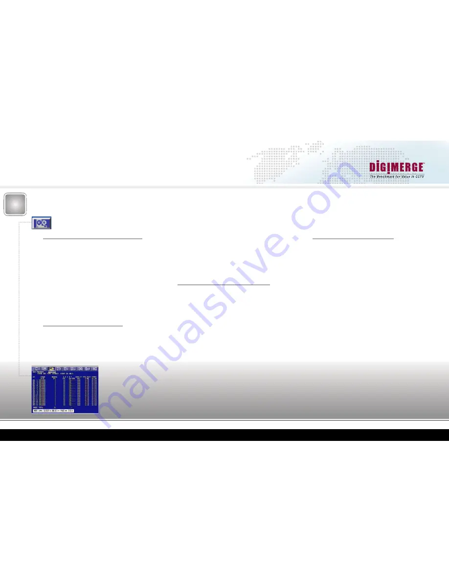
Setting Event (alarm/motion detection) Record IPS
The Event IPS Settings are only used with an Event is trig-
gered, for example an internally detected motion event, or an
external alarm contact
Please refer to Chart#1 for Maximum record IPS (images per
second) per channel for each resolution
Move right to highlight the values located below the
“Event IPS”
Column
Use the
“F-” (auto) or “F+” (freeze)
keys to decrement or incre-
ment the highlighted Event IPS values
Repeat this process for each Channel
The Sum of these IPS values cannot exceed the Maximum IPS
for the desired resolution
For the VCE400 to record on Motion (detection) Events, you
will need to enable the Event Record, in the Event Menu (Refer
to the Motion Detection Setup Section 5a)
Setting Continuous/Event Record Quality
Quality N Settings are used during continuous/normal recordings
Quality E Settings are used only when Event recording is trig-
gered, such as internally detected motion, or an external alarm
contact
Setting Event Recording (A/L/M) Triggers
These settings dictate what type of events will trigger the
VCE400 to record; by default these are all enabled
“O” indicates the option is enabled, “-“ indicates the option is
disabled
“A”
indicates an externally triggered alarm contact (dry contact,
such as a door trigger, or motion sensor)
“L”
indicates the pre-alarm buffer will be recorded in the event
of a Video Loss
“M”
indicates an internal pixel based motion detection trigger
(standard motion detection)
Move right to highlight the value located below the
“Event A/L/
M”
Column
Use the
“F-”
(auto) or
“F+”
(freeze) keys to modify the high-
lighted Event A/L/M values
Repeat this process for each Channel
For more information on these features, refer to the VCE400
Series Manual, under the “6.4.7 Sensor Input” section
Press
“Spot/ESC”
2 times
Move down to
“Save and Exit”
and press
“status/home/enter”
Move right to highlight the values located below the
“Quality
N/E”
Column
Use the
“F-” (auto) or “F+” (freeze)
keys to modify the high
lighted Record Quality values
“B”
Indicates Best Quality recording
“H”
Indicates High Quality recording
“N”
Indicates Normal Quality recording
Repeat this process for each Channel
Setting Pre-Alarm and Post Alarm Record Times
The Pre-Alarm time reflects the amount of video that is re-
corded before an Event is triggered (Maximum setting is
5 seconds; this setting is global for all the cameras)
The Post-Alarm time is the duration of the recording after the
event has stopped triggering (Maximum setting is 60 seconds;
this setting is camera independent)
Move right to highlight values located below the
“Pre/Post Time”
Column
Use the
“F-” (auto) or “F+” (freeze)
keys to decrement or incre-
ment the highlighted Pre/Post Time values
Repeat this process for each Channel


