


5-9
Chapter 5
5.1.16 Cues and MIDI ....................................................................
There are two separate areas of MIDI control.
1)
A cue can have a MIDI Patch attached to it, and will output that MIDI when fired. The MIDI Patch must be created separately in the
Setup Menu / MIDI Patches
panel or in the Cue editor software. Switching the MIDI scope on pops up a panel prompting for a MIDI
Patch button to be pressed, which will then be linked to the cue whose scope is currently displayed.
2)
The firing of cues can be controlled by incoming MIDI messages on channel 16, and can cause these same messages to be output in
addition to any MIDI Patches included in (1) above.
The MIDI Input Control button allows the cue system to respond to the following incoming MIDI messages:-
General Purpose Controller A (Controller 16); Values 0 to 127 will fire cues 1 to 128
General Purpose Controller B (Controller 17); Values 0 to 127 will fire cues 129 to 256
General Purpose Controller C (Controller 18); Values 0 to 127 will fire cues 257 to 385.
General Purpose Controller D (Controller 19); Values 0 to 125 will fire cues 385 to 510.
General Purpose Controller D (Controller 19); Value 126 will fire the previous cue in list.
General Purpose Controller D (Controller 19); Value 127 will fire the next cue in list.
MIDI Output causes the above messages 1 to 510 to be sent whenever a cue button is pressed. Previous and Next buttons do not output
MIDI messages of their own.
5.1.17 MIDI Patches .......................................................................
The console's main MIDI port is known as MIDI port T. If your D5T is fitted with the combination MIDI/GPI/GPO card it can also have 2
more MIDI ports A & B (Each card provides 16 extra MIDI channels - A1 to A16 on the first card and B1 to B16 on the second card.)
The port letter may be prefixed on any line of the MIDI Patches Editor before the MIDI channel number (separated by spaces). If the port
letter is omitted, Port T is assumed.Touching the
MIDI Patch
button in the
Setup
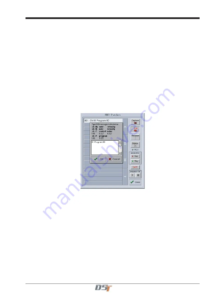
menu opens the MIDI Patches panel which allows any
MIDI program change, controller change, note on or off message to be recorded and played back manually or against timecode.
This panel works in a very similar way to the main cue system and an indicator on the MIDI panel shows when any MIDI data is being
received.
When the
Capture
button is pressed a text panel is displayed and any incoming MIDI controller or program change information is
recorded. There is also a list of required syntax for entering the text manually.
The captured text may be edited or new text entered into an existing patch by touching the
Edit
button and typing. This text is then
compiled into the required stream of MIDI data when OK is pressed. Errors are reported at this stage.
The MIDI Patches can be made Safe from Cue recall globally by pressing the
SAFE
button on the panel - this button is duplicated in the
Scope section of the Cue List itself.
The correct format for the messages is as follows:
(See the Cue Editor section of this manual for an alternative method of entering this information.)
Note On
The MIDI Port Number (Port T is assumed if there is no entry here)
A 2 digit MIDI Channel number between 01 and 16
N+ to indicate Note On
A note number between 0 and 127
A velocity value between 0 and 127
eg.
A
01
N+
60
127
Summary of Contents for D5T
Page 1: ...Operation Manual Issue A September 2004 Software Versions 2 4...
Page 2: ......
Page 10: ......
Page 11: ...Chapter 1 1 1 Chapter 1 Getting Started...
Page 12: ...Chapter 1 1 2...
Page 32: ...Chapter 2 2 1 Chapter 2 Inputs and Console Channels...
Page 33: ...Chapter 2 2 2...
Page 58: ...Chapter 3 3 1 Chapter 3 Busses and Outputs...
Page 59: ...3 2 Chapter 3...
Page 68: ...4 1 Chapter 4 Chapter 4 Master Section...
Page 69: ...Chapter 4 4 2...
Page 91: ...5 1 Chapter 5 Chapter 5 The Cue List...
Page 92: ...Chapter 5 5 2...
Page 111: ...Chapter 6 6 1 Chapter 6 Automation...
Page 127: ...7 1 Chapter 7 Chapter 7 Effects...
Page 128: ...7 2 Chapter 7...
Page 135: ...8 1 Chapter 8 Chapter 8 Troubleshooting...
Page 136: ...Chapter 8 8 2...
Page 139: ...A 1 AppendixA Appendix A D5TC Theatre Masters Controller...
Page 140: ...A 2 Appendix A...
Page 147: ...B 1 Appendix B Appendix B Multiple Console Setups Inc Redundant Engines...
Page 148: ...B 2 Appendix B...
Page 162: ...B 16 Appendix B Standalone PC Screen Appearance...


