


Chapter 1
1-17
1.3.11 EQ ........................................................................................
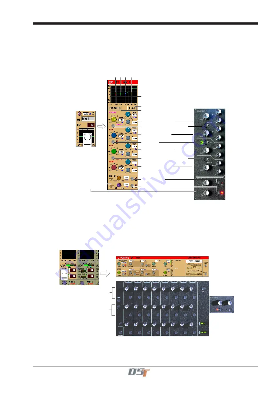
The EQ section comprises four user-configurable parametric filters and a pair of swept High-pass and Low-pass filters.
The EQ is accessed by touching the on screen display to
Assign
the channel (
the colour changes to orange
) and then using the
controls on the right hand side of the input module.
When a control is adjusted the expanded view seen below appears in the input screen but this view can be seen at any time by touching
the EQ response graph on the screen.
NOTE:
If the expanded view does not appear when a control is adjusted open the
System / Options
panel and press the
Automatically
expand EQ view when adjusted button.
Response Graph
Filter Centre Frequencies
Preset Selector
Parametric 1 (Yellow)
Curve Select for Parametric 1
Curve Select for Parametric 4
EQ In/Out
Parametric 2 (Blue)
Parametric 3 (Green)
Parametric 4 (Red)
Hipass / Lopass Filters
Reset EQ
Lopass In/Out
Hipass In/Out
Note:
The four band EQ and each of the filters have their own in/out switches.
The type of filter used by bands one and four can be changed by successive presses of the
Curve Select
button
for that band. There are
three possible settings for each band.
1.3.12 Dynamics ............................................................................
The dynamics are accessed by touching the words
Comp
or
Gate
just below the EQ graph on screen to open the dynamics panel.
The worksurface controls beneath the screen control the various parameters. Touching the panel again will close it.
Dedicated
Threshold
controls and
In/Out
switches can be found on the right hand side of the input section worksurface. These can
control the Assigned channel's dynamics whether the on screen dynamics panel is open or not.
Gate Controls
Compressor Controls
The third row of buttons in the input section can be assigned to any of the dynamics on/off switches. Hold the
Assign Switch
button on
the left of the input section and touch the dynamics section on the screen. The selected control is shown by the
Status Display.
Note
: These switches can also be assigned to other functions -
See section 2.1.3
Summary of Contents for D5T
Page 1: ...Operation Manual Issue A September 2004 Software Versions 2 4...
Page 2: ......
Page 10: ......
Page 11: ...Chapter 1 1 1 Chapter 1 Getting Started...
Page 12: ...Chapter 1 1 2...
Page 32: ...Chapter 2 2 1 Chapter 2 Inputs and Console Channels...
Page 33: ...Chapter 2 2 2...
Page 58: ...Chapter 3 3 1 Chapter 3 Busses and Outputs...
Page 59: ...3 2 Chapter 3...
Page 68: ...4 1 Chapter 4 Chapter 4 Master Section...
Page 69: ...Chapter 4 4 2...
Page 91: ...5 1 Chapter 5 Chapter 5 The Cue List...
Page 92: ...Chapter 5 5 2...
Page 111: ...Chapter 6 6 1 Chapter 6 Automation...
Page 127: ...7 1 Chapter 7 Chapter 7 Effects...
Page 128: ...7 2 Chapter 7...
Page 135: ...8 1 Chapter 8 Chapter 8 Troubleshooting...
Page 136: ...Chapter 8 8 2...
Page 139: ...A 1 AppendixA Appendix A D5TC Theatre Masters Controller...
Page 140: ...A 2 Appendix A...
Page 147: ...B 1 Appendix B Appendix B Multiple Console Setups Inc Redundant Engines...
Page 148: ...B 2 Appendix B...
Page 162: ...B 16 Appendix B Standalone PC Screen Appearance...


