6. FPG TOOLS
Page 81
© 2007 DH Instruments, a Fluke Company
Purging consists of opening a valve that exchanges gas in the lubricating volume
for a fixed amount of time. The valve is then closed for a fixed amount of time to
allow for stability. The change in humidity between the beginning and end of the cycle
is used to determine if the purge process should be repeated. Purging is repeated
until the humidity criterion is met or the
<Operation Abort>
function is used.
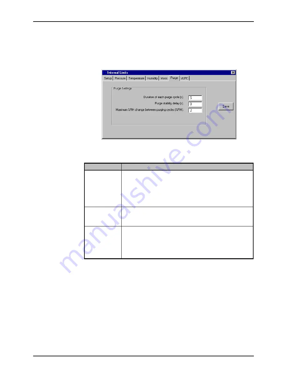
Figure 38. <Internal Limits> <Purge>
Table 25. <Internal Limits> <Purge>
Options
LABEL
DESCRIPTION
Duration of each
purge cycle
(numeric entry field)
Enter a value that specifies how long gas will be removed from the
lubricating volume. In gauge mode, if the limit is sufficiently long, the
lubrication pressure will approach ATM. In absolute mode, the lubrication
pressure will slowly approach vacuum. Completely removing all gas in the
lubricating volume is the goal of purging only when the gas has been
changed. Typically, the goal is to obtain a stable humidity value in the
proper range. Removing a small amount of gas several times is all that is
needed to accomplish this task.
Purge stability
delay
(numeric entry field)
The time in seconds that FPG Tools should wait prior to comparing the
before and after humidity values. If the time is not long enough to allow the
FPG regulators to re-fill the volume, the purging process will take longer
than necessary or may not obtain proper humidity conditions.
Maximum %RH
change between
purging cycles
(numeric entry field)
Maximum change between the humidity at the beginning of the purge and
the humidity after the stability test. If the humidity change exceeds this limit,
the purge cycle is repeated. With each successive purge cycle, the change
in humidity should decrease because the volume should approach the
target equilibrium humidity. Using a value too small for this field will keep
the FPG in a continuous purge loop. On the other hand if the value is too
large, the volume will not be properly purged.
6.6.4.7
<VLPC>
The minimum and default control limits of the VLPC are defined on this tab.
The active control settings used to determine a “Ready” condition are defined by
the active test sequence or the current setup in the
<Settings>
(see Section
6.6.1) option. When the hold setting is set too small, the limits setup on this tab
determine the actual criterion imposed on the pressure “Ready/Not
Ready” indication. Each time a new pressure range is set, the default hold limits
specified on this tab are set.
There are separate default values for each gauge and absolute pressure range.
The available ranges and the corresponding percent of range hold limits are
available only after
[Run], [Run Monitor]
is used and the VLPC is enabled. The
available ranges are dependent on the specific setup of the VLPC.


