2
Hardware Installation
39
Note:
An IDE cable with a standard 40-pin connector (without the
keying mechanism) can be installed in the shrouded IDE header.
Be extremely careful to match the colored edge of the ribbon
with pin 1 of the header.
Connecting the Hard Disk Cable
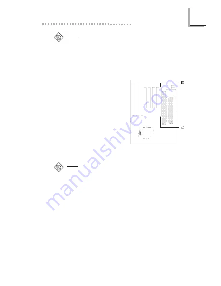
1. If you are connecting two hard
drives, install the 40-pin
connector of the IDE cable into
the primary shrouded IDE
header (connector J22). If you
are adding a third or fourth IDE
device, install the 40-pin
connector of the other IDE cable
into the secondary shrouded IDE
header (connector J18).
2. Install the other 40-pin header
connector(s) into the device with the colored edge of the
ribbon cable aligned with pin 1 of the drive edge connector(s).
Note:
Refer to your disk drive users manual for information about
selecting proper drive switch settings.
Adding a Second IDE Hard Drive
When using two IDE drives, one must be set as the master and the
other as the slave. Follow the instructions provided by the drive
manufacturer for setting the jumpers and/or switches on the drives.
We recommend that you use Enhanced IDE or ATA-2 and ATA-3
hard drives be from the same manufacturer. In a few cases, drives
from two different manufacturers will not function properly when
used together. The problem lies in the hard drives, not the system
board.
Summary of Contents for 586ITBD
Page 1: ...586ITBD Rev BO0 System Board User s Manual 34220829...
Page 6: ...1 Introduction CHAPTER...
Page 15: ...2 Hardware Installation CHAPTER...
Page 19: ...2 Hardware Installation 19 Board Layout square denotes pin 1...
Page 47: ...3 Award BIOS Setup Utility CHAPTER...
Page 71: ...4 Supported Softwares CHAPTER...
Page 76: ...A DIM and SIM Modules APPENDIX...
Page 79: ...B Memory and I O Maps APPENDIX...
Page 82: ...C System Error Report APPENDIX...
Page 85: ...D Troubleshooting APPENDIX...


