


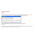


Schematic Menu Layout
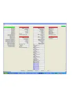
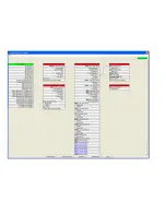
You will end up with the schematic shown below. It has the following format:
•
The 1st column contains the Domain Controller.
•
The 2nd column contains AV sources.
•
The 3rd column contains AV surround receivers and video processors.
•
The 4th column contains displays and speakers.
For each component:
•
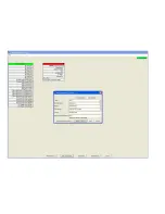
The top line displays the name of the AV component. If you click on the name, the Info Menu will pop up - providing you more
information about the AV component. The small letter "i" to the right of the name is there to remind you that you can get
"information" about the AV component by clicking here (or anywhere on the name). If you want to
Delete
the AV component from
this project, click on the "x" at the far right of this line.
•
The top set of ports will be outputs and they will be "right justified".
•
The 2nd set of ports will be inputs and they will be "left justified"
•
The 3rd set of ports will be one or more control ports (e.g. "IR Control" and/or "Serial Control").
•
The last port will be "Power Sync" port and it will be written as one of:
•
"Power Sync (not needed)" if the AV component does have discrete power commands
•
"Power Sync (recommended)" if the AV component does not have discrete power commands
•
"Power Sync (high)" if the port is wired to a Video Sync input on the Domain 3000
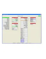
At this point, you have added the components. Now it is time to wire the components together in software - just like they are physically
wired.
Color key to Wire Types
As you begin adding wires, you will notice that they have a color associated with them based on their wire type.
Color
Wire
Blue
Video
Green
Audio
Summary of Contents for Domain 3000
Page 16: ......
Page 21: ......
Page 24: ......
Page 29: ......
Page 33: ...Red IR Control Yellow Power Sense Silver Serial...
Page 34: ......
Page 38: ......
Page 40: ......
Page 42: ......
Page 44: ......
Page 46: ......
Page 48: ......
Page 50: ......
Page 52: ......
Page 54: ......
Page 55: ...Subwoofer wire added below...
Page 56: ......
Page 58: ......
Page 60: ......
Page 62: ......
Page 64: ......
Page 66: ......
Page 68: ......
Page 70: ......
Page 72: ......
Page 74: ......
Page 80: ......
Page 87: ......
Page 89: ......
Page 95: ...Acrobat will now have the schematic Click File Print...
Page 102: ......


