


this as a possible problem.
c. The Device Description File of one of the AV component is the wrong Device Description File for that component, OR,
the IR codes in the Device Description File for that component are incorrect. See #10 below to eliminate this as a
possible problem.
d. The IR codes in the Device Description File for that component are not associated with the Destiny commands
properly. See #11 below to eliminate this as a possible problem.
e. If the AV component does not have discrete power on/off commands, then the "Power Sync" signal may not be
working properly. See #12 below to eliminate this as a possible problem.
f. The "post delay" times in the Device Description File are incorrect. There was not enough "dead time" between
sending the command to it to turn it on and sending the command to it to select one of its inputs. See #13 below to
eliminate this as a possible problem.
7.
Use the steps below to eliminate each of the problems above
.
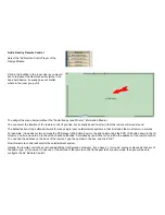
8. On the Entertainment menu, click on the "Advanced" button (located under the volume and channel buttons). This button
is only available after a source has been turned on. On the left hand side is the list of AV components that Ubiquity
thinks it should control to set up the path. If the AV component that is not working is not listed, then the problem is "a"
above. You need to go back to the Schematic menu of the Design Module and set up the AV paths properly. To see how
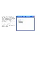
the software thinks you have set up the path, open Check My Destiny, expand the "Entertainment" section (it will be 2nd
from the bottom). Expand "Theater room", expand "Theater", and click on "Show last 20 cmds". You may have to resize
the window to make it easier to view. It will list the commands it took to set up the path from the source to the display
and/or speakers.
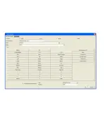
9. At this point, you have identified that the software tried to set up the correct path from the source to the display and/or
speakers, and you have identified one or more AV components that are not being controlled properly. We need to
determine if an IR signal is getting to the AV component. On the Advanced Entertainment Menu, select the component
on the left that is not working properly. A field of button will appear on the right. Find the "Power On" button. Click it. If the
power turns on, you have eliminated "b" and "c". If not, check your wiring or substitute a Blinking IR emitter and see that
it blinks. Note that just because it blinks, does not mean that IR is being transmitted. We once ran across a set of
blinkers where the emitter blinked, but the IR was not being sent. Also check that the IR blinker is plugged into the
proper port of the Domain Controller (as configured into the software). Finally, make sure that it is pointing at the IR
receiver of the AV component. Place a large piece of cardboard in front of the AV component. Make a small hole in it
and place the hole in front of the IR emitter. Use the remote control that came with the AV component to turn the
component on and off. If you succeed, then the IR emitter is in the correct place.
10. At this point, you have working IR emitters, and if the IR commands on the Advanced Entertainment menu control the AV
component properly, you have eliminated "d", so please continue to #11. Otherwise, one or more of the IR codes is
incorrect. Open the Info menu of the AV component by clicking on the name of the AV component on the Schematic
menu of the Design Module as described above. Make sure you have the right Device Description File (i.e., the "File
Summary of Contents for Domain 3000
Page 16: ......
Page 21: ......
Page 24: ......
Page 29: ......
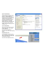
Page 33: ...Red IR Control Yellow Power Sense Silver Serial...
Page 34: ......
Page 38: ......
Page 40: ......
Page 42: ......
Page 44: ......
Page 46: ......
Page 48: ......
Page 50: ......
Page 52: ......
Page 54: ......
Page 55: ...Subwoofer wire added below...
Page 56: ......
Page 58: ......
Page 60: ......
Page 62: ......
Page 64: ......
Page 66: ......
Page 68: ......
Page 70: ......
Page 72: ......
Page 74: ......
Page 80: ......
Page 87: ......
Page 89: ......
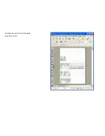
Page 95: ...Acrobat will now have the schematic Click File Print...
Page 102: ......


