background image

Get
ting Star

ted

Connections

Set
tin
g

s
Pla
ybac

k

Remot

e Contr

ol

ZONE2

Tr

oubleshooting

Specifications

ENGLISH

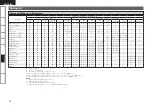
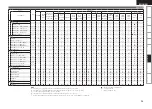
Surround

F

 :  Mode selectable in initial status

D

 :  Mode fixed when “AFDM” is “ON”

S

 :  Selectable mode

A

 :  Non-selectable mode

NOTE

:

z

1:  This mode is not available when the surround back speaker setup is set to “None”.

z

2:  This mode is not available when the surround back speaker setup is set to “1spkr” or “None”.

z

3:  Can be set when “Amp Assign” is set to “Normal”.

z

4:  This mode is not available when the front height speaker setup is set to “None”.

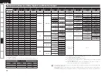
Differences in Surround Mode Names Depending on the Input Signals

Button

Note

Input signals

ANALOG

 LINEAR 

PCM / 

WAV

WMA (Windows 

Media Audio) / 

MP3 / MPEG-4 

AAC / FLAC

DTS-HD

DTS

DOLBY

DOLBY DIGITAL

MULTI CH PCM

Surround Mode

DTS-HD 

Master 

Audio

DTS-HD 

High 

Resolution 

Audio

DTS 

EXPRESS

DTS ES 

DSCRT  

(With Flag)

DTS ES 

MTRX  

(With Flag)

DTS 

(5.1ch)

DTS 

96/24

DOLBY 

TrueHD

DOLBY 

DIGITAL 

Plus

DOLBY 

DIGITAL 

EX (With 

Flag)

DOLBY 

DIGITAL EX 

(With no 

Flag)

DOLBY 

DIGITAL 

(5.1/5/4ch)

DOLBY 

DIGITAL 

(4/3ch)

DOLBY 

DIGITAL 

(2ch)

PCM 

 (multi ch)

PCM  
(2ch)

STANDARD

DTS SURROUND

DTS-HD MSTR

A

A

A

F

A

A

A

A

A

A

A

A

A

A

A

A

A

A

A

DTS-HD HI RES

A

A

A

A

F

A

A

A

A

A

A

A

A

A

A

A

A

A

A

DTS ES DSCRT6.1

z

z

3

A

A

A

A

A

A

F D

A

A

A

A

A

A

A

A

A

A

A

A

DTS ES MTRX6.1

z

z

3

A

A

A

A

A

A

A

F D

A

A

A

A

A

A

A

A

A

A

A

DTS SURROUND

A

A

A

A

A

A

S

S

F

A

A

A

A

A

A

A

A

A

A

DTS 96/24

A

A

A

A

A

A

A

A

A

F

A

A

A

A

A

A

A

A

A

DTS (–HD) + PL

g

x CINEMA

z

z

3

A

A

A

S

S

S

S

S

S

S

A

A

A

A

A

A

A

A

A

DTS (–HD) + PL

g

x MUSIC

z

z

3

A

A

A

S

S

S

S

S

S

S

A

A

A

A

A

A

A

A

A

DTS (–HD) + PL

g

z HEIGHT

z

4

A

A

A

S

S

S

S

S

S

S

A

A

A

A

A

A

A

A

A

DTS EXPRESS

A

A

A

A

A

F

A

A

A

A

A

A

A

A

A

A

A

A

A

DTS (–HD) + NEO:6

z

z

3

A

A

A

S

S

S

A

S

S

S

A

A

A

A

A

A

A

A

A

DTS NEO:6 CINEMA

S

S

S

A

A

A

A

A

A

A

A

A

A

A

A

A

S

A

S

DTS NEO:6 MUSIC

S

S

S

A

A

A

A

A

A

A

A

A

A

A

A

A

S

A

S

DOLBY SURROUND

DOLBY TrueHD

A

A

A

A

A

A

A

A

A

A

F

A

A

A

A

A

A

A

A

DOLBY

A

A

A

A

A

A

A

A

A

A

A

F

A

A

A

A

A

A

A

DOLBY DIGITAL EX

z

z

3

A

A

A

A

A

A

A

A

A

A

A

A

S

S

S

S

A

A

A

DOLBY (D+) (HD) +EX

z

z

3

A

A

A

A

A

A

A

A

A

A

S

S

A

A

A

A

A

A

A

DOLBY DIGITAL

A

A

A

A

A

A

A

A

A

A

A

A

S

F

F

F

A

A

A

DOLBY (D) (D+) (HD) +PL

g

x CINEMA

z

z

3

A

A

A

A

A

A

A

A

A

A

S

S

F D

S

S

S

A

A

A

DOLBY (D) (D+) (HD) +PL

g

x MUSIC

z

z

3

A

A

A

A

A

A

A

A

A

A

S

S

S

S

S

S

A

A

A

DOLBY (D) (D+) (HD) +PL

g

z HEIGHT

z

4

A

A

A

A

A

A

A

A

A

A

S

S

S

S

S

S

A

A

A

DOLBY PRO LOGIC 

g

z HEIGHT

z

4

S

S

S

A

A

A

A

A

A

A

A

A

A

A

A

A

S

A

S

DOLBY PRO LOGIC 

g

x CINEMA

z

z

3

S

S

S

A

A

A

A

A

A

A

A

A

A

A

A

A

S

A

S

DOLBY PRO LOGIC 

g

x MUSIC

z

z

3

S

S

S

A

A

A

A

A

A

A

A

A

A

A

A

A

S

A

S

DOLBY PRO LOGIC 

g

x GAME

z

z

3

S

S

S

A

A

A

A

A

A

A

A

A

A

A

A

A

S

A

S

DOLBY PRO LOGIC 

g

 CINEMA

S

S

S

A

A

A

A

A

A

A

A

A

A

A

A

A

S

A

S

DOLBY PRO LOGIC 

g

 MUSIC

S

S

S

A

A

A

A

A

A

A

A

A

A

A

A

A

S

A

S

DOLBY PRO LOGIC 

g

 GAME

S

S

S

A

A

A

A

A

A

A

A

A

A

A

A

A

S

A

S

DOLBY PRO LOGIC

S

S

S

A

A

A

A

A

A

A

A

A

A

A

A

A

S

A

S

Inf
or

mation

Summary of Contents for AVR-990

Page 1: ...n GUI Menu Operation vpage 25 GUI Menu Map vpage 24 Remote Control Unit Operations vpage 84 Fran ais Utilisez ce manuel en m me temps que le guide d utilisation affich sur l cran GUI Interface graphiq...

Page 2: ...ion when moving the cart apparatus combination to avoid injury from tip over 13 Unplug this apparatus during lightning storms or when unused for long periods of time 14 Refer all servicing to qualifie...

Page 3: ...hwah NJ 07430 2041 Tel 800 497 8921 2 IMPORTANT NOTICE DO NOT MODIFY THIS PRODUCT This product when installed as indicated in the instructions contained in this manual meets FCC requirements Modificat...

Page 4: ...ng Files Stored on a Computer 60 Playing Files Stored on USB Memory Devices 60 Listening to Napster 61 Listening to Rhapsody 63 Operations During Playback 65 Adjusting the Master Volume 65 Turning Off...

Page 5: ...ngs condensation dew may form on the operating parts inside the unit causing the unit not to operate properly If this happens let the unit sit for an hour or two with the power turned off and wait unt...

Page 6: ...If the battery fluid should leak carefully wipe the fluid off the inside of the battery compartment and insert new batteries Remove the batteries from the remote control unit if it will not be in use...

Page 7: ...tQUICK SELECT buttons 78 yMASTER VOLUME control knob 65 uAUDYSSEY DYNAMIC VOLUME indicator 71 iHD AUDIO indicator 67 oMaster volume indicator Q0Display Q1Remote control sensor 3 Q2SOURCE SELECT knob 2...

Page 8: ...is lights to indicate that party mode has started as Attendee Q1AUDYSSEY MULTEQ indicators Lighting is as follows depending on the setting of Dynamic EQ vpage 71 and Dynamic Volume vpage 72 When Dynam...

Page 9: ...OTE CONTROL jacks 21 rTRIGGER OUT jacks 21 tDOCK CONTROL jack 15 ySpeaker terminals 12 uSIGNAL GND terminal 16 iAC inlet 23 oAC OUTLETS 23 Q0Digital audio connectors 15 18 Q1HD Radio antenna terminals...

Page 10: ...VIDEO SELECT button 47 Q9Front height speaker on off button 70 W0Tuner operation buttons 55 W1MULTEQ button 71 W2Number buttons 0 9 10 84 W3MAIN ZONE power buttons 23 W4SLEEP TIMER button 77 W5INPUT M...

Page 11: ...tal connections Coaxial digital cable Optical digital connections Optical cable Analog connections stereo surround R L R L Audio cable Analog connections monaural for subwoofer Audio cable Speaker con...

Page 12: ...put terminal HDMI Component video S Video Video Use the terminals according to the devices to be connected This function automatically converts various formats of video signals input to the AVR 990 in...

Page 13: ...boveH z1 22 30 z2 22 45 z3 90 110 Surround speaker Front height speaker Point slightly downwards 2 to 3 feet 60 to 90 cm GAs seen from the sideH Front speaker When 7 1ch Front Height Speaker Connected...

Page 14: ...nnels played Normal Surround Back Speakers Normal Surround Back L Speaker Connect to the L speaker terminal Set Surround Back vpage 33 to 1spkr b b Normal Not connected Set Surround Back vpage 33 to N...

Page 15: ...e rear panel or if the and sides touch each other v Protection Circuit Never touch the speaker terminals while the power supply is connected Doing so could result in electric shock Use speakers with a...

Page 16: ...tion System HDCP The AVR 990 supports HDCP High bandwidth Digital Contents Protection HDCP is a copyright protection technology for digital video signals The devices connected to the AVR 990 must also...

Page 17: ...udio specifications of the connected device regarding permissible inputs Connecting to a Device Equipped with a DVI D Terminal When an HDMI DVI conversion cable sold separately is used the HDMI video...

Page 18: ...ons With the default settings the iPod can be used connected to the VCR iPod connector R L R L 065 7 0 0 10 5 7 0 1 13 7 0 065 4 7 0 065 6 0 6 0 3 065 065 0 9 Blu ray Disc player DVD player Connecting...

Page 19: ...ave the reverse effect of increasing noise In this case it is not necessary to connect the ground line Video Cassette Recorder Select the terminal to use and connect the device R L R L R L R L 3 065 6...

Page 20: ...onnect the device R L R L R L R L 3 3 065 6 0 6 0 7 0 7 0 065 015 015 6 0 6 0 065 7 0 7 0 0 10 5 7 0 1 13 065 4 7 0 065 4 7 0 Digital video recorder NOTE To record video signals through the AVR 990 us...

Page 21: ...on the Home Tuner antenna near a south facing window to receive the best signal For details see Listening to SIRIUS Satellite Radio vpage 54 When making connections also refer to the operating instruc...

Page 22: ...istent satellite signal the antenna must be positioned correctly Use the following map to determine which area you are in and position the antenna accordingly n q w e r t SOUTH NORTH WEST SKY EAST HOR...

Page 23: ...alog signals input from the external input EXT IN terminal set Input Mode vpage 48 to EXT IN EXT IN can also be selected with INPUT MODE on the remote control unit Set as Necessary Connections to Othe...

Page 24: ...volume control on the subwoofer to control subwoofer volume If the subwoofer volume sounds low use the volume control provided on the subwoofer to adjust the volume NOTE When speakers have been conne...

Page 25: ...browser Required system Broadband Internet connection Modem Router When using the AVR 990 we recommend you use a router equipped with the following functions Built in DHCP server This function automa...

Page 26: ...N ON or MAIN OFF 1 Press OFF or ON STANDBY The power is set to the standby mode 2 Press POWER The power indicator turns off and so does the power Turning the Power Off Turning the Power On Button loca...

Page 27: ...ck Check Audyssey Auto Setup measurement results This item is only displayed after Audyssey Auto Setup procedure has been performed 32 Manual Setup Use this to make various types of detailed settings...

Page 28: ...g ui b List n Selected item Use p or ENTER to switch z3 z2 z1 z7 z10 z9 z4 History item z5 Currently selected setup item z6 History item z7 Operation guidance text z8 Operation step z9 Illustration z1...

Page 29: ...o p to select the input source icon then press ENTER The input source is set and the source selection menu is turned off The currently selected input source is highlighted is displayed when using a co...

Page 30: ...age 71 72 are enabled Use the included setup microphone DM A409 to perform Audyssey Auto Setup procedure Measurements are performed by placing the calibrated microphone successively at multiple positi...

Page 31: ...dle of the gain knob s range Low Pass Filter setting Low Pass Filter Setting to Off or Maximum Highest Frequency Phase setting 0 Standby mode setting Off 5 Mount the setup microphone on a tripod or st...

Page 32: ...ront speakers The sound is output from front speakers B when measuring the front speakers The sound is output simultaneously from front speakers A and B when measuring the front speakers Subwoofer Sur...

Page 33: ...d to STEP4 Measure at a total of 6 positions including the main listening position and positions around it It is possible to stop the settings with five positions or fewer but for better results we re...

Page 34: ...Not all speakers could be detected The front L speaker was not properly detected Connect the included setup microphone to the SETUP MIC jack of the AVR 990 Check the speaker connections Too much noise...

Page 35: ...l Level Check Crossover Freq Check EQ Check The measurement result of each speaker is displayed When you selected EQ Check press ui to select the Correction curve you want to check Audyssey or Audysse...

Page 36: ...o Small Subwoofer can automatically set to Yes Perform when setting the speakers manually or when changing settings made in Audyssey Auto Setup Making the Speaker Settings Speaker Setup Default settin...

Page 37: ...the same when it is output from each speaker Test Tone Start Output test tone Front L Front Height L Center Front Height R Front R Surround R S Back Rz S Back Lz Surround L Subwoofer Select the speake...

Page 38: ...od we recommend that you press POWER to turn off jOFF the power When the HDMI Control setting has been changed always turn off the power to the connecting devices afterwards and then turn back on The...

Page 39: ...ings are underlined Setting items Setting contents 2ch Direct Stereo Continued Crossover Outputs at below set frequency each speaker s bass signal output from the subwoofer 40Hz 60Hz 80Hz 90Hz 100Hz 1...

Page 40: ...CLASS B 172 16 0 0 172 31 255 255 CLASS C 192 168 0 0 192 168 255 255 Subnet Mask When connecting an xDSL modem or terminal adapter directly to the AVR 990 input the subnet mask indicated in the docum...

Page 41: ...language setting Network Standby Set the network function on off during standby ON Network is on during standby Main unit operable with a network compatible controller OFF Suspend network function dur...

Page 42: ...rade Notification Display a notification message on the AVR 990 s GUI screen when downloadable firmware is released with Add New Feature The notification message is displayed for about 20 seconds when...

Page 43: ...evel Settheamountofattenuation when muting is on Full The sound is muted entirely 40dB The sound is attenuated by 40 dB down 20dB The sound is attenuated by 20 dB down Set the audio to playback with Z...

Page 44: ...display during adjustment Bottom Display at the bottom Top Display at the top OFF Turn display off When the master volume display is hard to see when superimposed on movie subtitles set to Top NET USB...

Page 45: ...ing Trigger Out 2 Remote ID Set when you operate another DENON AV amplifier with the remote control unit of the AVR 990 Match the remote control unit you are using with the remote ID of the AVR 990 1...

Page 46: ...grade will be displayed When Not Registered is displayed on the Add New Feature screen you cannot upgrade To use the upgrade function you should purchase an upgrade package from the DENON website To p...

Page 47: ...et Channels so that They are not Displayed When Tuning Preset Skip vpage 49 Giving Names to Preset Stations Preset Name vpage 50 iPod vpage 49 NET USB Media Server USB Napster and Rhapsody vpage 49 n...

Page 48: ...are output to the monitor The audio signals input from the analog digital and EXT IN connectors are not output to the monitor When control dock for iPod is used as the input source assignment of the H...

Page 49: ...nt input sources are as shown below Input source CD DVD HDP TV SAT CBL VCR Default setting Coax 3 Coax 1 None Opt 1 Coax 2 None Input source DVR V AUX SIRIUS Default setting Opt 2 Opt 3 None When cont...

Page 50: ...ayback This can be set when i p Scaler is set to anything other than OFF Aspect Set the aspect ratio for the video signals output to the HDMI This can be set when the input source is DVD HDP TV SAT CB...

Page 51: ...s Setting contents Input Mode Set the audio input modes for the different input sources Auto Automatically detect input signal and perform playback HDMI Play only signals from HDMI input Digital Play...

Page 52: ...me per image 5s 60s 5s This can be set when the input source is NET USB Setting items Setting contents Repeat Make settings for repeat mode All Repeat all files One Repeat the current file OFF Cancel...

Page 53: ...o not Match is displayed and the password does not change This can be set when the input source is SIRIUS For any channel set the radio reception limits Setting items Setting contents A1 G8 Select the...

Page 54: ...tructions of the connected components when playing them External devices can be controlled by remote control unit vpage 84 Operating the Connected Devices by Remote Control Unit When a DENON control d...

Page 55: ...be checked by pressing STATUS during playback The time default 30 sec for which the GUI menus are displayed can be set at GUI iPod vpage 41 Press uio p to return to the original screen Press OFF or ON...

Page 56: ...er or The Best of XM programming to your SIRIUS tuner enabling you to enjoy the most popular programming among both services The Best of packages are not available to SIRIUS or XM Canada subscribers a...

Page 57: ...ons Display Status EXCELLENT Signal strength is excellent GOOD Signal strength is good WEAK Signal strength is weak NO SIGNAL No signal 2 Adjust the position of the antenna until SIGNAL EXCELLENT is s...

Page 58: ...with auto tuning tune it in manually When tuning in stations manually press and hold TUNING to change frequencies continuously The time default 30 sec for which the GUI menu is displayed can be set GU...

Page 59: ...1 MHz F1 F8 90 1 MHz G1 G8 90 1 MHz n 1 Press SHIFT to select the memory block A to G 2 Press CHANNEL to select the desired preset station NOTE If the station signal weakens while receiving a digital...

Page 60: ...Art Function When a WMA Windows Media Audio MP3 or MPEG 4 AAC file includes album art data the album art can be displayed while the music files are playing For music files in WMA Windows Media Audio...

Page 61: ...etter vpage 66 n n n There are many Internet radio stations on the Internet and the quality of the programs they broadcast as well as the bit rate of the tracks varies widely Generally the higher the...

Page 62: ...o clear then press MEMORY 3 Press o to select Remove The selected Internet radio station is cleared To cancel the operation without clearing the station press p b Presetting Internet Radio Stations Pr...

Page 63: ...ic settings must be made in order to play music files vpage 22 Before starting you must launch the computer s server software and set the files as server contents For details see the operating instruc...

Page 64: ...After inputting the Username and Password select OK then press ENTER If the Username and Password match the top menu for Napster is displayed Username Input characters GLower case charactersH abcdefg...

Page 65: ...ter Library Top 100s New Releases Radio Napster Playlists Staff Picks Genres 1 7 Napster Search by Artist Search by Arbums Search by Track You can search by artist name album name or track name b 2 Us...

Page 66: ...ord may not contain underscores _ Press RETURN to cancel the input When Cancel input is displayed select Yes then press ENTER Playback uiop STATUS ENTER RETURN DEVICE SELECT 1 DEVICE SELECT 2 SOURCE S...

Page 67: ...e ui to select Add to my library then press ENTER or p The track is entered in the Library 1 Use ui to select Rating then press ENTER or p 2 Use o p to select the rating then press ENTER Use ui to sel...

Page 68: ...ack on the main unit The sound from the speakers and pre out connectors is automatically cut NOTE To prevent hearing loss do not raise the volume level excessively when using headphones Remove your he...

Page 69: ...they are displayed in alphabetical order If it is not possible to search the list unsorted list is displayed To cancel press ui or SEARCH b This operation is convenient for choosing items from the men...

Page 70: ...olby Digital DTS etc In the case of standard playback of multi channel sources the AVR 990 recognizes the format of the multi channel audio input signal and automatically operates the appropriate deco...

Page 71: ...he signals bypass the tone control circuitry for high quality sound The sound is output to the same channels as the input signal Input signal The indication contents of the display Analog signal PCM 2...

Page 72: ...l LFE 10dB 0dB For proper playback of the different sources we recommend setting to the values below Dolby Digital sources 0dB DTS movie sources 0dB DTS music sources 10dB Center Image Assign center c...

Page 73: ...e ES DSCRTz2 Play the surround back signals included in the 6 1 channel DTS source n n Setting items Setting contents Surround Parameters Continued PLgx CINEMAz3 Generate and play the surround back si...

Page 74: ...cs ON Use the Dynamic EQ equalizer OFF Do not use the Dynamic EQ equalizer After performing Audyssey Auto Setup the Dynamic EQ setting automatically becomes ON is displayed when set to ON When MultEQ...

Page 75: ...ame Setting Set Dynamic Volume equalizer effect Midnight High setting affects volume the most causing all sounds to be of equal loudness Evening Middle setting prevents loud and soft sounds from being...

Page 76: ...e original sound before compression It also corrects the sense of volume of the bass to obtain richer sound with compressed audio signals This is displayed on the GUI menu and can be set when the inpu...

Page 77: ...e Volume Level n Audio Input Signal Shows information about audio input signals Surround Mode The currently set surround mode Signal The input signal type fs The input signal s sampling frequency Form...

Page 78: ...hannel signals Digital audio signals input to the HDMI connectors are not output to the REC OUT connectors so connect using the OPTICAL or COAXIAL connectors Sources selected with the REC OUT mode are...

Page 79: ...ns for the connected equipment to check the settings Carryout steps 1 and 2 should any of the equipment be plugged out b b 3 Switch the television input to the HDMI connected to the AVR 990 4 Switch t...

Page 80: ...dB will change the setting to OFF b When a headphone jack is inserted the headphone channel level can be adjusted With this function you can set the AVR 990 so that the power is automatically switche...

Page 81: ...the party mode after it has started To participate in the party mode perform the operation described below 1 Press PARTY Enter Party Mode is displayed An error message is displayed when you are not co...

Page 82: ...terminal device Playing Contents on a Computer Media Server Playing Contents on a Mobile Terminal Device 1 From the mobile terminal device browse the media server in the same network and choose the c...

Page 83: ...0 33 z1 Entering the IP address Checking the IP address You can operate the AVR 990 using a browser z1 Operating the AVR 990 with a Browser Web Control Function 5 Operate GExample 1H Main zone control...

Page 84: ...Example 5H Net Audio operating screen z19 Click the menu from which you want to play z20 Click v to select the preset channel you want to play z21 Click to stop play z22 When registering presets click...

Page 85: ...using high quality pin plug cables for audio connections in order to prevent noise When the input source to which the digital input connectors OPTICAL COAXIAL are assigned is selected in ZONE2 playbac...

Page 86: ...choose the input source Operation on the remote control unit Press INPUT SOURCE SELECT 4 Adjust the item below Adjust the Volume Operation on the main unit q Press ZONE2 REC SELECT w Turn MASTER VOLU...

Page 87: ...ation VDP Video Disc Player can be preset when DEVICE SELECT 2 is set to DVD HDP The preset memory can be set for one component only among the following TV DVD HDP DVR VCR SAT CABLE and CD Depending o...

Page 88: ...SB TV TV DVD HDP DVD player or Blu ray disc player DVR VCR Digital video recorder or video deck SAT CBL Satellite receiver or cable TV CD CD player 3 Operate the component For details refer to the com...

Page 89: ...ns as the button for the device for which punch through is set TV GSpecial RemarksH q Only one device can be set in the preset memory for each mode When a new preset code is registered the existing co...

Page 90: ...ds the DVD remote control buttons may have different function names Check beforehand Front DEVICE SELECT ON SOURCE Power on Standby 1 Play 2 Stop 3 Pause 6 7 Manual search fast reverse fast forward CH...

Page 91: ...ns to operate other devices 3 Press BAND and DYNAMIC VOLUME at the same time The indicator starts flashing 4 Refer to the table below and input the number corresponding to the device to be assigned De...

Page 92: ...ries and Lucas Films The 6 1 channels of sound including surround back channels provide improved sound positioning and expression of space DTS Surround DTS Digital Surround DTS Digital Surround is the...

Page 93: ...ts proprietary AL24 Processing an analog waveform reproduction technology to support the 192 kHz sampling frequency AL24 Processing Plus thoroughly suppresses quantization noise associated with D A co...

Page 94: ...Auto S 0 dB S ON S S OFF A A A DTS SURROUND S D D D D D NOTE3 S OFF A S 0 dB S ON S S OFF A A A DTS 96 24 S D D D D D NOTE3 S OFF A S 0 dB S ON S S OFF A A A DTS HD S D D D D D NOTE3 S OFF A S 0 dB S...

Page 95: ...S S DTS NEO 6 A A A A A A S 0 3 A S OFF S OFF S S S DOLBY DIGITAL A A S A A A A A S OFF S OFF S S A DOLBY DIGITAL Plus A A S A A A A A S OFF S OFF S S A DOLBY TrueHD A A S A A A A A S OFF S OFF S S A...

Page 96: ...A A A A A S S F A A A A A A A A A A DTS 96 24 A A A A A A A A A F A A A A A A A A A DTS HD PLgx CINEMA z2 z3 A A A S S S S S S S A A A A A A A A A DTS HD PLgx MUSIC z1 z3 A A A S S S S S S S A A A A A...

Page 97: ...HEIGHT z4 A A A A A A A A A A A A A A A A A S A MULTI IN DOLBY EX z1 z3 A A A A A A A A A A A A A A A A A S A MULTI CH IN 7 1 z1 z3 A A A A A A A A A A A A A A A A A F D 7 1 A DIRECT DIRECT S S S S S...

Page 98: ...ENT z3 A COMPONENT z3 ON A S 1080p S A S VIDEO S VIDEO A COMPONENT A S VIDEO A S VIDEO ON z1 A S 1080p S A A S S VIDEO S S VIDEO S S VIDEO ON A S 1080i 480p S A S COMPONENT A COMPONENT z3 A S VIDEO A...

Page 99: ...age Power switches off suddenly while you are using the AVR 990 the power indicator will flash in red at intervals of approximately 2 seconds The protection circuit will be activated depending upon th...

Page 100: ...nition 1080i 720p and progressive 480p 576p video signals are not down converted Set the player to interlace 480i 576i signals Check the Video Select setting 13 14 68 47 Picture cannot be recorded The...

Page 101: ...that is copyright protected Files that are copyright protected cannot be played on this set Set and computer are connected by USB cable The set s USB port cannot be used for connection to a computer 5...

Page 102: ...Call SIRIUS z is displayed Channels are not subscribed to If you subscribe to the channel you can receive the channel SUBSCRIPTION UPDATED is displayed While updating contract information Enter Lock...

Page 103: ...160 W 6 ohms 1 kHz with 0 7 T H D Dynamic power 130 W x 2ch 8 ohms 180 W x 2ch 4 ohms Output connectors Center Surround Surround back 6 16 ohms Front A or B 6 16 ohms A B 8 16 ohms Analog Input sensi...

Page 104: ...169 KTV 038 137 139 147 151 153 L LG 012 030 036 127 151 Logik 033 LXI 010 012 155 M M S 155 Magnasonic 049 Magnavox 028 037 047 054 056 137 151 155 Majestic 033 Marantz 046 137 151 152 155 Maxent 11...

Page 105: ...129 Kenwood 080 128 KLH 058 129 136 Koss 067 134 L Landel 147 Lasonic 141 Lenoxx 133 144 LG 055 076 077 095 138 142 Liquid Video 134 Liteon 068 146 M Magnavox 047 062 127 135 145 Memorex 053 126 Micr...

Page 106: ...ilco 032 Philips 024 032 041 061 Philips Magnavox 041 Pilot 031 Profitronic 013 Pulsar 025 Q Quarter 029 Quartz 029 Quasar 032 R RadioShack 008 024 031 Radio Shack Realistic 024 029 030 031 032 033 Ra...

Page 107: ...Stargate 020 041 Starquest 020 041 Supercable 044 Supermax 046 T Time Warner 004 Tocom 031 Torx 049 Toshiba 040 Trans PX 044 Tristar 046 TS 049 Tusa 020 041 TV86 024 U Unika 014 015 United Cable 028 U...

Page 108: ...Denon Brand Company D M Holdings Inc Printed in China 5411 10344 009D www denon com...

Reviews: