/Kits/1296-144CK.doc
12
8/15/2011
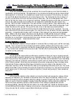
When complete you may retest the RX and TX section and re-adjust the IF levels as
desired. If complete, attach the lid and the 4 screws or you may also wish to install some or all of
the user options. They are listed starting on the bottom of this page.
Completion
This completes the assembly and testing of the 1296-144CK. You now have enough
knowledge of how this assembly works that implementing it into a complete working transverter
system should not be a technical problem.
The receive conversion gain is limited for a reason. This receive section will not overload in
a RF dense environment. If the transverter is to be used in a high performance terrestrial or EME
set up, a mast mount LNA that has better noise figure performance will be desired. If so,
additional filtering may be required and the use of the IF amplifier may need to be omitted. Simply
adding a LNA to the front of the transverter will improve the noise figure but will degrade its
dynamic range by the amount of gain added. It is not recommended to add an LNA unless it is
mast mounted. If a higher power amplifier is added, also consider and additional filter and isolator.
DEM 1296 -144 User Options and performance Improvements:
Add an external preamplifier for noise figure improvement.
If a better noise figure is desired, simply placing a LNA with a modest gain at the antenna
will solve that problem. Understand that the addition of gain in front of this stock transverter will
degrade the IMD performance, and reduce the dynamic range of the transverter by more than the
amount of gain added. You may get a way with doing nothing more than adjusting the RXIF gain
control if you operate in a non-hostile RF environment. If your LNA is a ultra low noise unit, it most
likely will not have the IP3 performance the transverter has. It will overload before any component
in the transverter will. So, your receive system now becomes limited by it’s external LNA’s
performance. If you increase the gain performance of your external LNA, (25-30 db) you may
consider bypassing the transverters LNA completely because it’s IP3 performance is totally
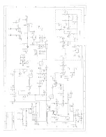
controlled by the external LNA. To do so, remove L5, L31, C59, R31, and R30 from the circuit.
Then connect a short piece of coax between the RX antenna and C63. Be sure to keep it as short
as possible and solder the grounds.
Another option is to remove the IF amplifier. If you need to reduce the gain by less than 10
dB, remove IC5 and R18. Then you may use a 100 pF disc capacitor and place it from where the
input and output leads of IC5 was. You may then still adjust the RXIF control to your desire.
Install / Remove RXIF gain stages:
This was briefly discussed in the external preamplifier section. For whatever reason, you
may require additional gain or have too much IF gain. IC5 can be installed or removed at any
time. Be sure of your systems performance when deciding to make a change. You are also not
limited to the supplied ERA 6 MMIC. You may choose a higher gain unit. The ERA 6 was chosen
for its IP3 output performance. Using this MMIC doesn’t degrade the transverters overall
performance. A high gain MMIC will not only reduce the IP3 by the difference in gain but will also
degrade the system if a lower IP3 output device is used. In the future, this MMIC will change as
soon as something better become available.
If changing or removing the MMIC, be sure to add or remove the correct choke and bias
resistor for the desired MMIC. The RXON signal is the same voltage that the transverter operates
on so calculate the new bias resistor based on that voltage.
Summary of Contents for 1296-144 CK
Page 16: ......


