/Kits/1296-144CK.doc
11
8/15/2011
problem in the TXRF section of the transverter. If the transverter does not appear saturated,
suspect a problem in the IF section.
Final Assembly
Check all screws and connectors for tightness. Place the top lid on the enclosure
and allow the unit to operate in receive for 1 hour with either a load or an antenna connected. The
unit will become warm to the touch. If you have a 23 cm signal and the IF transceiver connected,
you may notice some frequency drift. After the first hour of operation, the majority of frequency drift
is complete and the oscillator will be stable enough for netting the frequency if required. Remove
the cover and adjust C2 to match the frequency of a know signal or measure the LO frequency at
C17. If the desired frequency cannot be obtained before the oscillator either shuts off or becomes
unstable, determine if it is to high in frequency or to low. If it is to high, remove the LO shield and
compress the L1 inductor and readjust C2. If the frequency is to low, spread the coil slightly and
re-adjust C2. If the frequency is still to low a circuit modification will be required. The circuit
modification is described below but technical details are covered in our Design Note #16 found in
the library section of DEMI web site (www.downeastmicrowave.com). The modification is simple.
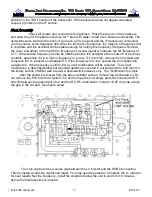
After the shield is removed from the base oscillator section, remove the crystal and L2. Do
not remove the PTC form the crystal!! Cut and remove the now empty pad still connected to R5
and R4 between the placement of L2 and the R4, R5 combination. Install a 10 pF chip cap across
the gap in the cut pad. See figure below.
The chip cap becomes a series cap between the L2 /crystal and the R4/R5 connection.
Then re-install L2 and the crystal and retest. You may need to spread or compress the L1 inductor
for best results. Net the frequency, install the shield and allow the unit to warm for 10 minutes
before the final adjustment is made.
Summary of Contents for 1296-144 CK
Page 16: ......


