HD50
- 8 -
V1.4
3.3
HD50GH
CONNECTIONS
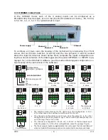
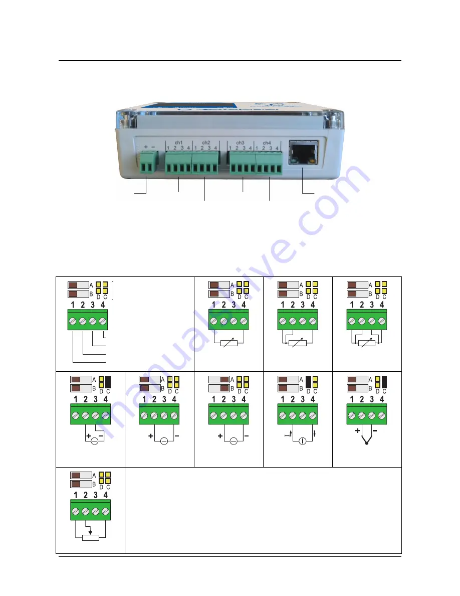
In the HD50GH model, each of the 4 analog inputs can be configured as a
Pt100/Pt1000, thermocouple, 0/4…20 mA (the shunt resistance is inside), -50…50 mV,
0…50 mV, 0…1 V, 0…10 V or potentiometric input.
To configure an input, open the housing of the instrument by unscrewing the 4 front
screws and set the two switches (A and B) and the two jumpers (C and D) located
above the input terminals as shown below. Next, complete the inputs configuration us-
ing the web server feature of the data logger (see the panel
SETTINGS >> INPUTS
in pa-
ragraph 5.1) or the HD35AP-S software (see the section
Data loggers configuration >>
Inputs setup
of the instructions of the software).
Pt100 / Pt1000
2 wires
Pt100 / Pt1000
3 wires
Pt100 / Pt1000
4 wires
0…50 mV
-50…50 mV
0…1 V
0…10 V
0…20 mA
4…20 mA
Thermocouple
K,J,T,N,E
Potentiometer
•
The switches A and B are set to the right only in the configuration 0…10 V;
in the other cases, the switches A and B are set to the left.
•
If a channel is configured as current input, close the jumper D; in the other
configurations, leave the jumper D open. The current input accepts any val-
ue in the range from 0 to 20 mA.
•
If a channel is configured as -50…50 mV, 0…50 mV or thermocouple input,
close the jumper C; in the other configurations, leave the jumper C open.
•
The thermocouple inputs are
not
isolated. Do not connect the internal USB port
when not isolated thermocouple probes are connected, to avoid ground loops.
GND (analog ground)
IN-
IN+
Excitation voltage
ch1
/
ch2
/
ch3
/
ch4
Power supply
Channel 1
Ethernet
Channel 3
Channel 2
Channel 4
Configuration
switches / jumpers
Summary of Contents for HD50 14b7P TC
Page 52: ...HD50 52 V1 4 NOTES ...
Page 53: ...HD50 53 V1 4 NOTE ...
Page 54: ...HD50 54 V1 4 NOTE ...
Page 55: ......


