HD50
- 7 -
V1.4
3
INSTALLATION
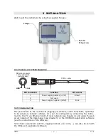
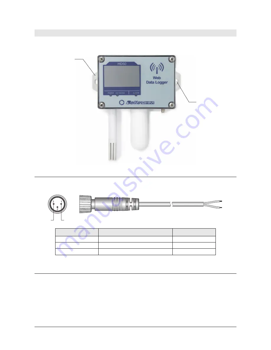
Wall mount the instrument by using the supplied flanges.
3.1
P
OWER SUPPLY
M8
CONNECTOR
M8 connector
Function
Wire color
1
Power supply positive (+Vdc)
Brown
2 Not
used
3
Power supply negative (GND)
Blue
3.2
C
ONFIGURATION
The parameters of the instrument (logging parameters, alarm thresholds, quantities
to be acquired, network settings, etc.) can be configured by connecting the instru-
ment to the PC via Ethernet or Wi-Fi local network (see chapter 4) and using the web
server feature of the data logger (see chapter 5) or the HD35AP-S application software
(see the instructions of the software).
Some basic parameters (alarms, logging interval, user code, …) can also be set with
the HDServer1 application software.
Flange
Hole for
fixing screw
+Vdc
GND
M8 male connector
of the instrument
(external view)
CPM8… cable
Summary of Contents for HD50 14b7P TC
Page 52: ...HD50 52 V1 4 NOTES ...
Page 53: ...HD50 53 V1 4 NOTE ...
Page 54: ...HD50 54 V1 4 NOTE ...
Page 55: ......


