HD50
- 31 -
V1.4
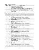
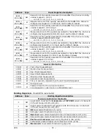
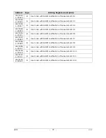
Address Type
Input Register description
1027 +
200 x (
N
-1)
B
Alarm for temperature with TC_E sensor
of channel
N
:
0=OFF, 1=lower threshold alarm, 2=higher threshold alarm.
1028 +
200 x (
N
-1)
SW Input value in
mV
of channel
N
(x10). Only if channel
N
is configured as
0…1 V
input.
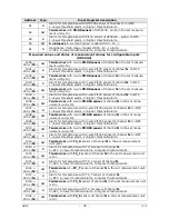
1029 +
200 x (
N
-1)
B
Alarm for channel
N
if the channel is configured as 0…1 V input:
0=OFF, 1=lower threshold alarm, 2=higher threshold alarm.
1030 +
200 x (
N
-1) SW
Input value in
mV
of channel
N
(x100). Only if channel
N
is configured
as
0…50 mV
input.
1031 +
200 x (
N
-1)
B
Alarm for channel
N
if the channel is configured as
0…50 mV input:
0=OFF, 1=lower threshold alarm, 2=higher threshold alarm.
1032 +
200 x (
N
-1)
SW Input value in
mA
of channel
N
(x100). Only if channel
N
is configured
as
4…20 mA input.
1033 +
200 x (
N
-1)
B
Alarm for channel
N
if the channel is configured as
4…20 mA input:
0=OFF, 1=lower threshold alarm, 2=higher threshold alarm.
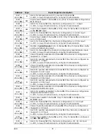
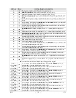
1034 +
200 x (
N
-1)
SW Position of
potentiometer
in % of channel
N
. Only if channel
N
is config-
ured as
potentiometric input.
1035 +
200 x (
N
-1)
B
Alarm for channel
N
if the channel is configured as
potentiometric input:
0=OFF, 1=lower threshold alarm, 2=higher threshold alarm.
1036 +
200 x (
N
-1) SW
Value of quantity associated to channel
N
if the channel is configured as
mapped 0…1 V input.
1037 +
200 x (
N
-1)
B
Alarm for quantity associated to channel
N
if the channel is configured as
mapped 0…1 V input:
0=OFF, 1=lower threshold alarm, 2=higher threshold alarm.
1038 +
200 x (
N
-1) SW
Value of quantity associated to channel
N
if the channel is configured as
mapped 0…50 mV input.
1039 +
200 x (
N
-1)
B
Alarm for quantity associated to channel
N
if the channel is configured as
mapped 0…50 mV input:
0=OFF, 1=lower threshold alarm, 2=higher threshold alarm.
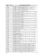
1040 +
200 x (
N
-1) SW
Value of quantity associated to channel
N
if the channel is configured as
mapped 4…20 mA input.
1041 +
200 x (
N
-1)
B
Alarm for quantity associated to channel
N
if the channel is configured as
mapped 4…20 mA input:
0=OFF, 1=lower threshold alarm, 2=higher threshold alarm.
1042 +
200 x (
N
-1) SW
Value of quantity associated to channel
N
if the channel is configured as
mapped potentiometric input.
1043 +
200 x (
N
-1)
B
Alarm for quantity associated to channel
N
if the channel is configured as
mapped potentiometric input:
0=OFF, 1=lower threshold alarm, 2=higher threshold alarm.
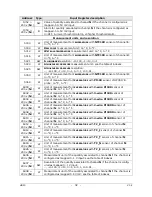
1044 +
200 x (
N
-1)
SW Input value in
mV
of channel
N
. Only if channel
N
is configured as
0…10 V
input.
1045 +
200 x (
N
-1)
B
Alarm for channel
N
if the channel is configured as 0…10 V input:
0=OFF, 1=lower threshold alarm, 2=higher threshold alarm.
1046 +
200 x (
N
-1)
SW Value of quantity associated to channel
N
if the channel is configured as
mapped 0…10 V input.
1047 +
200 x (
N
-1)
B
Alarm for quantity associated to channel
N
if the channel is configured as
mapped 0…10 V input:
0=OFF, 1=lower threshold alarm, 2=higher threshold alarm.
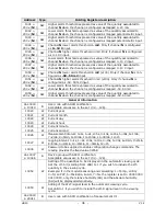
1050 +
200 x (
N
-1)
SW Input value in
mV
of channel
N
(x100). Only if channel
N
is configured
as
-50…50 mV
input.
1051 +
200 x (
N
-1)
B
Alarm for channel
N
if the channel is configured as
-50…50 mV input:
0=OFF, 1=lower threshold alarm, 2=higher threshold alarm.
Summary of Contents for HD50 14b7P TC
Page 52: ...HD50 52 V1 4 NOTES ...
Page 53: ...HD50 53 V1 4 NOTE ...
Page 54: ...HD50 54 V1 4 NOTE ...
Page 55: ......

