HD50
- 36 -
V1.4
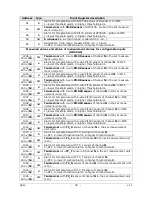
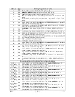
Address Type
Holding Register description
1041 +
200 x (
N
-1)
SW Higher alarm threshold expressed as value of the quantity associated to
channel
N
when the channel is configured as mapped 4…20 mA.
1042 +
200 x (
N
-1)
SW Lower alarm threshold expressed as value of the quantity associated to
channel
N
when the channel is configured as mapped potentiometric input.
1043 +
200 x (
N
-1)
SW Higher alarm threshold expressed as value of the quantity associated to
channel
N
when the channel is configured as mapped potentiometric input.
1044 +
200 x (
N
-1) SW
Channel
N
lower alarm threshold in
mV
. Only if channel
N
is configured
as
0…10 V
input.
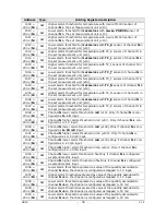
1045 +
200 x (
N
-1)
SW Channel
N
higher alarm threshold in mV. Only if channel
N
is configured
as 0…10 V input.
1046 +
200 x (
N
-1)
SW Lower alarm threshold expressed as value of the quantity associated to
channel
N
when the channel is configured as mapped 0…10 V input.
1047 +
200 x (
N
-1) SW
Higher alarm threshold expressed as value of the quantity associated to
channel
N
when the channel is configured as mapped 0…10 V input.
1050 +
200 x (
N
-1)
SW Channel
N
lower alarm threshold in
mV
(x100). Only if channel
N
is con-
figured as
-50…50 mV
input.
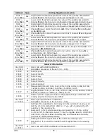
1051 +
200 x (
N
-1)
SW Channel
N
higher alarm threshold in mV (x100). Only if channel
N
is
configured as
-50…50 mV input.
1052 +
200 x (
N
-1) SW
Lower alarm threshold expressed as value of the quantity associated to
channel
N
when the channel is configured as mapped -50…50 mV.
1053 +
200 x (
N
-1)
SW Higher alarm threshold expressed as value of the quantity associated to
channel
N
when the channel is configured as mapped -50…50 mV.
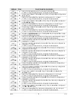
General information
da 10000
a 10019
B
User code with ASCII codification.
Acceptable values are in the set {32,…,126}.
10020 W
Current
year
10021 W
Current
month
10022
W
Current day
10023 W
Current
hour
10024
W
Current minute
10025
W
Current second
10026 W
Measurement interval: 0=1s, 1=2s, 2=5s, 3=10s, 4=15s, 5=30s, 6=1min,
7=2min, 8=5min, 9=10min, 10=15min, 11=30min, 12=1h
10027 W
Logging interval: 0=1s, 1=2s, 2=5s, 3=10s, 4=15s, 5=30s, 6=1min, 7=2min,
8=5min, 9=10min, 10=15min, 11=30min, 12=1h
10036 W
Password to be supplied to enable configuration change commands. The
reading provides the fixed value 32768.
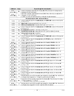
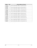
da 10037
a 10046
B
Device group with ASCII codification.
Acceptable values are in the set {32,…,126}.
10052 W
Setting of the quantities to be displayed in the automatic viewing cycle.
Set the i-th bit (starting from LSB) to 1 if you wish to include the i-th
quantity in the viewing cycle.
Example
: if in the model measuring and calculating: 1=Temp., 2=RH,
3=Td, 4=PVP, 5=Mix.Ratio, 6=AH, 7=Tw, the register is set to 0000 0000
0010 0010, only the relative humidity (RH) and the absolute humidity
(AH) will be displayed alternatively.
10053 W
Adding of the Wi-Fi signal level in the automatic viewing cycle.
Set LSB to 1 if you wish to include the Wi-Fi signal level in the viewing
cycle.
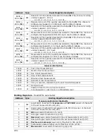
da 20000
a 20011
B
User code with ASCII codification of measurement #1.
Summary of Contents for HD50 14b7P TC
Page 52: ...HD50 52 V1 4 NOTES ...
Page 53: ...HD50 53 V1 4 NOTE ...
Page 54: ...HD50 54 V1 4 NOTE ...
Page 55: ......

