background image

GHM GROUP – Delta OHM

  |  Delta Ohm S.r.l. a socio unico 

Via Marconi 5  |  35030 Caselle di Selvazzano  |  Padova | ITALY  
Phone +39 049 8977150  |  Fax +39 049 635596 
www.deltaohm.com  |  [email protected] 


V1.4 

11/07/2018 


Summary of Contents for HD50 14b7P TC

Page 1: ...Operating manual Web Data Logger HD50 series Keep for future reference www deltaohm com English Companies Brands of GHM ...

Page 2: ...URATION 7 3 3 HD50GH CONNECTIONS 8 4 CONNECTION TO THE NETWORK 9 4 1 HD35AP CFR21 SOFTWARE OPTION 10 5 WEB SERVER 11 5 1 SETTINGS MENU 12 5 2 MONITOR MENU 18 5 3 CONNECTIVITY MENU 20 5 4 FILES MENU 27 6 MODBUS 28 7 TECHNICAL CHARACTERISTICS 38 8 ADAPTER FOR CO2 CALIBRATION 43 9 INSTRUMENT STORAGE 44 10 SAFETY INSTRUCTIONS 44 11 ORDERING CODES 45 ...

Page 3: ...ed to Internet the data can be regularly sent to an FTP address to the Cloud and via e mail For each detected quantity two alarm thresholds can be set by the user Exceeding a threshold is signaled acoustically by means of the internal buzzer visually by lighting the alarm LED on the front panel and remotely by sending alarm e mails An alarm hysteresis and a delay in the generation of the alarm can...

Page 4: ...nd HD50 TCV models or M12 connec tor for temperature RH probe probe with cable HD50 TC models 5 M12 connector for illuminance probe only HD50 I models 6 CO2 fixed probe only HD50 B models 7 RJ45 connector for Ethernet connection 8 Power supply input terminal header for HD50 H M8 connector for other models 9 Terminal header inputs only HD50 H ...

Page 5: ...ging is active CLOUD symbol indicates that the data logger is configured to send the data to the Cloud It blinks until the connection with the server is established HDServer1 symbol indicates that the data logger is configured to send the data to the HDServer1 software operating in a PC server of the local network It blinks until the connection with the software is established Ethernet WiFi symbol...

Page 6: ...C Probe with cable M12 connector TV Fixed vertical probe without cable TCV Fixed sensors photometric probe with cable Available HD50 series models MEASURES INPUTS OPTIONAL LCD L G Model NTC10K Pt100 RH Patm CO2 Lux Number of M12 connectors Built in sensors Custom Graphic HD50 N 1 TC 1 HD50 N 2 TC 2 HD50 N 3 TC 3 HD50 N TV HD50 1N TC 1 HD50 17P TC 1 HD50 1N TV HD50 14bN TV HD50 14bN TC 1 Patm HD50 ...

Page 7: ...lds quantities to be acquired network settings etc can be configured by connecting the instru ment to the PC via Ethernet or Wi Fi local network see chapter 4 and using the web server feature of the data logger see chapter 5 or the HD35AP S application software see the instructions of the software Some basic parameters alarms logging interval user code can also be set with the HDServer1 applicatio...

Page 8: ... 2 wires Pt100 Pt1000 3 wires Pt100 Pt1000 4 wires 0 50 mV 50 50 mV 0 1 V 0 10 V 0 20 mA 4 20 mA Thermocouple K J T N E Potentiometer The switches A and B are set to the right only in the configuration 0 10 V in the other cases the switches A and B are set to the left If a channel is configured as current input close the jumper D in the other configurations leave the jumper D open The current inpu...

Page 9: ...P S it allows connecting one data logger at a time or HDServer1 it allows connecting several data loggers simultaneously application soft ware and the MySQL database management system included in the HD35AP S soft ware package must be installed Thanks to the availability of two TCP IP virtual ports each of which can operate with proprietary for the connection with HD35AP S software or MODBUS TCP I...

Page 10: ...the instrument configuration and viewing of data in the database Each user can be assigned a different password for using the software There are also three levels of access Administrator Super user and stan dard User for each level the allowed operations can be defined The HD35AP CFR21 option works with USB hardware key to be connected to any PC con nected to the same local network of the PC in wh...

Page 11: ...GS INFO Data logger general information CONFIGURATION Modbus address user code and belonging group MEASURES Selection of the quantities to be displayed LOGGING Logging settings ALARMS Alarm thresholds and hysteresis UNITS Units of measurement CHANNELS INPUTS Selection of the quantities to be displayed with the Monitor function ex cept HD50GH or configuration of the input channels only HD50GH MONIT...

Page 12: ...e instrument o model serial number o user code o belonging group o Wi Fi signal level only if the Wi Fi interface is active o behaviour when the internal memory is full cyclic overwriting or not o logging status o buzzer activation status o Modbus address firmware version o logging interval o measurement interval o calibration date CONFIGURATION panel Setting of Modbus address user code and belong...

Page 13: ...ging interval is greater than the measuring interval the average of the mea surements acquired during the logging interval will be stored The Erase Memory button allows erasing the data in the data logger memory Select the quantities to be displayed cyclically on the display Custom name Select to define a custom name Button to refresh the settings Press Apply to send the changes to the data logger...

Page 14: ...threshold is 10 C and the upper threshold is 60 C the hysteresis in C is equal to 60 10 x2 100 1 C The alarm is generated after the set delay time or immediately if the no delay op tion is selected If the alarm condition disappears before the delay time has elapsed the alarm is not generated Press Apply to send the changes to the data logger Lower threshold Upper threshold Button to refresh the se...

Page 15: ...sts the quantities available to the left and the quantities to be displayed to the right The quantities are displayed in the order in which they appear in the list on the right Temperature unit of measurement Press Apply to send the changes to the data logger Pressure unit of measurement Activates all the quantities Delete the quantity selected in the list on the right Moves upwards or downwards t...

Page 16: ...oltage input with associated physical quantity Mapped Voltage 0 50mV 0 50 mV voltage input with associated physical quantity Mapped Current 4 20mA 4 20 mA current input with associated physical quantity Mapped Potentiometer potentiometric input with associated physical quantity Voltage 0 10V 0 10 V voltage input Mapped Voltage 0 10V 0 10 V voltage input with associated physical quantity Voltage 50...

Page 17: ...tity corresponding to the input value X1 e g 0 0 C X2 value of input signal in the second point e g 20 00 mA Y2 value of the physical quantity corresponding to the input value X2 e g 70 0 C x x 4 00mA 1 y x 20 00mA 2 y 70 0 C 1 y 0 0 C 2 Press the key Set to apply to the measure an offset equal to the opposite of the cur rently measured value the current measure becomes equal to zero Press the key...

Page 18: ...V format MEASURES panel Displays the current value of the quantities only those selected for logging The measurements in alarm are highlighted with a red background The L and H sym bols indicate whether the lower L or higher H threshold has been exceeded CHART panel Displays the graphs of the measurements acquired by the Monitor function The quanti ties can be displayed on the same graph or in sep...

Page 19: ...nual scroll interval X axis manual scroll buttons Pause Start automatic scroll Displays the data in the From To interval Single all quantities on the same graph Multiple a graph for each quantity Y axis minimum and maximum values Automatic or manual Y axis scale Selection of the quantities to be plotted Selection of the information to be displayed in the graphs Button for exporting data log or csv...

Page 20: ...r of a data logger with IP address 192 168 1 2 in the web browser you need to type 192 168 1 2 40 The WLAN LAN module has two TCP IP ports For each of the two ports set the fol lowing o the protocol select Proprietary TCP proprietary protocol or Modbus TCP o the port number the numbers set by default are 5100 for the proprietary proto col and 502 for the Modbus TCP IP protocol o the number of sock...

Page 21: ...o obtain the address automatically dynamic IP address via DHCP protocol Dynamic Host Configuration Protocol Note it is suggested to use a static IP for the communication with the HD35AP S soft ware with a web browser or via MODBUS TCP IP protocol because the client devices PC PLC do not automatically detect any changes in the IP address of the data log ger Similarly select whether to manually ente...

Page 22: ...ter the user name of the account o Account Password enter the password of the account o SMTP Server Address enter the outgoing mail server name supplied by your e mail service provider o SMTP Server Port enter the outgoing mail server port number supplied by your e mail service provider standard 25 o SMTP Authentication select the checkbox in order to authenticate e mails sent o Language select th...

Page 23: ...via e mail of all data memorized in a determined interval of time indicate the interval starting instant in the Start Date Time field and the interval ending instant in the Stop Date Time field then press Execute Note sending e mail and MODBUS TCP IP communication are mutually ex clusive activities The e mails are not sent if a MODBUS TCP IP communica tion is active FTP panel Setting of the FTP se...

Page 24: ...r 2 hours 4 hours 8 hours 12 hours 1 day 2 days 4 days 1 week o In the Data Mode field select the format of the data sent via FTP LOG format for the database and displaying with the Monitor function of the web server CSV format for Excel o To require the sending via FTP of all the data memorized subsequently to a given instant indicate the instant in the Date Time Upload field and press Execute o ...

Page 25: ...iod field The available options are Real Time 15 min 30 min 1 hour 2 hours 4 hours 8 hours 12 hours 1 day 2 days 4 days 1 week o To require the sending to the Cloud of all the data memorized subsequently to a given instant indicate the instant in the Date Time Upload field and press Exe cute o To require the sending to the Cloud of all data memorized in a determined inter val of time indicate the ...

Page 26: ...ata memorized sub sequently to a given instant indicate the instant in the Date Time Upload field and press Execute o To require the sending to the HDServer1 software of all data memorized in a de termined interval of time indicate the interval starting instant in the Start Date Time field and the interval ending instant in the Stop Date Time field then press Execute CLOCK panel Setting of clock s...

Page 27: ... the files to be imported multiple files can be se lected The data loggers corresponding to the imported files appear in the Device list select a data logger and press View data to display the data CHART panel Displays the graphs of the imported measurements See the CHART panel of the MONITOR menu SETUP panel Setting of the quantities and information to be displayed in the graphs of the imported m...

Page 28: ...n integer e g if the content of the register is 184 the value is to be intended as 18 4 o x100 centesimal value expressed as an integer e g if the content of the reg ister is 500 the value is to be intended as 5 00 The commands for requesting units of measurement return an index according to the correspondence indicated in the table below Indexes of the units of measurement Index Unit of meas Inde...

Page 29: ...IAL VAPOR PRESSURE in hPa x100 7 B Partial vapor pressure alarm 0 OFF 1 lower threshold alarm 2 higher threshold alarm 8 SW MIXING RATIO in g Kg x10 9 B Mixing ratio alarm 0 OFF 1 lower threshold alarm 2 higher threshold alarm 10 SW ABSOLUTE HUMIDITY in g m3 x10 11 B Absolute humidity alarm 0 OFF 1 lower threshold alarm 2 higher threshold alarm 12 SW WET BULB TEMPERATURE in the set measurement uni...

Page 30: ...et meas urement unit x10 1007 200 x N 1 B Alarm for temperature with 2 wire Pt1000 sensor of channel N 0 OFF 1 lower threshold alarm 2 higher threshold alarm 1008 200 x N 1 SW TEMPERATURE with 3 wire Pt1000 sensor of channel N in the set meas urement unit x10 1009 200 x N 1 B Alarm for temperature with 3 wire Pt1000 sensor of channel N 0 OFF 1 lower threshold alarm 2 higher threshold alarm 1010 20...

Page 31: ...shold alarm 1038 200 x N 1 SW Value of quantity associated to channel N if the channel is configured as mapped 0 50 mV input 1039 200 x N 1 B Alarm for quantity associated to channel N if the channel is configured as mapped 0 50 mV input 0 OFF 1 lower threshold alarm 2 higher threshold alarm 1040 200 x N 1 SW Value of quantity associated to channel N if the channel is configured as mapped 4 20 mA ...

Page 32: ... 3 wire Pt100 sensor of channel N 0 C 1 F 6004 200 x N 1 W Unit of measurement for TEMPERATURE with 4 wire Pt100 sensor of channel N 0 C 1 F 6006 200 x N 1 W Unit of measurement for TEMPERATURE with 2 wire Pt1000 sensor of channel N 0 C 1 F 6008 200 x N 1 W Unit of measurement for TEMPERATURE with 3 wire Pt1000 sensor of channel N 0 C 1 F 6010 200 x N 1 W Unit of measurement for TEMPERATURE with 4...

Page 33: ...ssociated to channel N if the channel is configured as mapped 50 50 mV see the table of indexes 6053 200 x N 1 SW Resolution of the quantity associated to channel N if the channel is config ured as mapped 50 50 mV 2 100 1 10 0 1 1 0 1 2 0 01 General information 10000 W Year of last measurement 10001 W Month of last measurement 10002 W Day of last measurement 10003 W Hour of last measurement 10004 ...

Page 34: ...E with Pt100 sensor of HP3517E probe in the set measurement unit x10 65 SW Higher alarm threshold for temperature with Pt100 sensor of HP3517E probe in the set measurement unit x10 80 SW ILLUMINANCE high range models HD50 I2 lower alarm threshold in lux 81 SW Illuminance high range models HD50 I2 higher alarm threshold in lux Measurement alarm thresholds for configurable inputs 1000 200 x N 1 SW L...

Page 35: ...her alarm threshold for temperature with TC_E sensor of channel N in the set measurement unit x10 1028 200 x N 1 SW Channel N lower alarm threshold in mV x10 Only if channel N is con figured as 0 1 V input 1029 200 x N 1 SW Channel N higher alarm threshold in mV x10 Only if channel N is con figured as 0 1 V input 1030 200 x N 1 SW Channel N lower alarm threshold in mV x100 Only if channel N is con...

Page 36: ...ty associated to channel N when the channel is configured as mapped 50 50 mV 1053 200 x N 1 SW Higher alarm threshold expressed as value of the quantity associated to channel N when the channel is configured as mapped 50 50 mV General information da 10000 a 10019 B User code with ASCII codification Acceptable values are in the set 32 126 10020 W Current year 10021 W Current month 10022 W Current d...

Page 37: ...tion of measurement 5 da 20060 a 20071 B User code with ASCII codification of measurement 6 da 20072 a 20083 B User code with ASCII codification of measurement 7 da 20084 a 20095 B User code with ASCII codification of measurement 8 da 20096 a 20107 B User code with ASCII codification of measurement 9 da 20108 a 20119 B User code with ASCII codification of measurement 10 da 20120 a 20131 B User cod...

Page 38: ...i security settings WEP64 WEP128 WAP WAP2 Alarm Acoustic by means of the internal buzzer LED on the front pan el sending of e mails Power supply External 7 30 Vdc no internal battery The PoE Power over Ethernet technology is not supported Consumption 40 mA 24 V 80 mA 12 V Display Optional custom or graphic LCD LED indicators Power supply Network connection LAN WLAN and Alarm Operating temperature ...

Page 39: ...NB I TCV Min 291 420 Max 906 640 T RH TD TW AH MR PVP PATM CO2 I HD50 H Min 615 220 Max 1 165 680 depends on the connected sensors 1 Quantities T temperature AH absolute humidity RH relative humidity MR mixing ratio TD dew point PVP partial vapour pressure TW wet bulb temperature PATM atmospheric pressure CO2 carbon dioxide I illuminance 2 A sample consists of multiple values a value for each quan...

Page 40: ...ble units of measurement hPa mbar mmHg inchHg mmH2O inchH2O atm Carbon dioxide CO2 Sensor Non Dispersive Infrared NDIR Measuring range B 0 5 000 ppm B2 0 10 000 ppm Resolution of the instrument 1 ppm Accuracy B 50 ppm 3 of the measure 25 C 1013 hPa B2 100 ppm 5 of the measure 25 C 1013 hPa Operating conditions 20 60 C 0 95 RH non condensing 850 1100 hPa Response time T90 120 s air speed 2 m s Stab...

Page 41: ...4 instrument reading error 0 5 f5 fatigue 0 5 Class B One year drift 1 Operating temperature 0 50 C Reference standard CIE n 69 UNI 11142 Relative spectral response of the illuminance sensor Wavelength nm Relative spectral response ...

Page 42: ...easuring range type K 200 1370 C type J 100 750 C type T 200 400 C type N 200 1300 C type E 200 750 C Resolution 0 1 C Accuracy excluding probe error type K 0 1 C 600 C type J 0 1 C 0 2 C 600 C type T 0 1 C type N 0 1 C 600 C 0 2 C 600 C type E 0 1 C 300 C 0 2 C 300 C Input 0 4 20 mA Shunt resistance Internal 50 Ω Resolution 16 bit Accuracy 2 µA Inputs 50 50 mV 0 50 mV 0 1 V and 0 10 V Input resis...

Page 43: ...r unscrew the probe filter screw the HD31 B3A adapter and connect the cylinder adjust the cylinder flow meter to get a constant flow between 0 3 and 0 5 l min CO2 calibration with a cylinder The calibration is performed with the aid of the HD35AP S software follow the in structions of the software ...

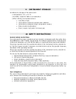
Page 44: ...s the specific measures described in this operating manual The proper operation and the operational safety of the instrument can be ensured on ly under the climatic conditions specified in this manual Do not use the instrument in places where there are Rapid ambient temperature variations that may cause condensation Corrosive or flammable gases Direct vibrations shocks to the instrument High inten...

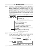
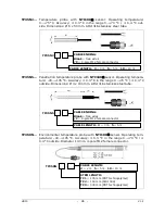
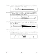
Page 45: ...ordered separately The Ethernet ca ble is not included Note see the table of available models Temperature probes with NTC10kΩ 25 C sensor TP35N1 Temperature probe with NTC10KΩ sensor Operating tempera ture 20 75 C Accuracy 0 3 C in the range 0 70 C 0 4 C outside Dimensions Ø 5 x 40 mm AISI 316 stainless steel tube TP35N1 CABLE ENDING Blank free wires C 4 pole M12 female connector CABLE LENGTH 3 3 ...

Page 46: ... x 100 mm AISI 316 stainless steel tube TP350N Environmental temperature probe with NTC10KΩ sensor Operating tem perature 40 105 C Accuracy 0 3 C in the range 0 70 C 0 4 C outside Diameter 14 mm 4 pole M12 female connector TP350N CABLE LENGTH 2 2 m 5 5 m 10 10 m STEM LENGTH TC1 135 mm PBT technopolymer TC2 150 mm AISI 304 TC3 335 mm PBT technopolymer TP35N5 CABLE ENDING Blank free wires C 4 pole M...

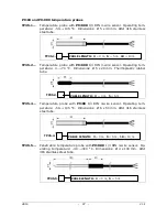
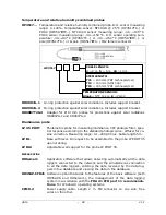
Page 47: ...nsions Ø 5 x 20 mm Thermoplastic rubber tube TP35 4 Temperature probe with Pt100 1 3 DIN 4 wire sensor Operating tem perature 50 105 C Dimensions Ø 6 x 50 mm AISI 316 stainless steel tube TP35 5 Penetration temperature probe with Pt1000 1 3 DIN 3 wire sensor Op erating temperature 40 300 C Dimensions Ø 4 x 100 mm AISI 316 stainless steel tube TP35 5 CABLE LENGTH 3 3 m 5 5 m TP35 4 CABLE LENGTH 3 3...

Page 48: ...m Cable length 2 m Shield in Inox PTFE Operating temperature 110 180 C TP472I W Stainless steel temperature probe 4 wire wire wound Pt100 sensor Stem dimensions Ø 3 x 300 mm Cable length 2 m Operating tempera ture 196 500 C Thermocouple temperature probe TP35K6 5 K type thermocouple temperature probe with isolated hot junction Operating temperature 50 750 C Accuracy class 1 according to IEC 60584 ...

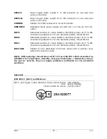
Page 49: ...rd photopic curve diffuser for co sine correction Measuring range 0 1 200 000 lux Cable length 5 m LP BL Base with level On request to be assembled to the probe LP PHOT 35 upon ordering LP BL3 Adjustable wall support for the probe LP PHOT 35 Accessories HDServer1 Application software that allows detecting automatically all the data loggers connected to the network and the simultaneous connection t...

Page 50: ...33 RH includes ring adapter for 14 mm diameter probes thread M12 1 HD11 Saturated solution to check Relative Humidity probes at 11 RH includes ring adapter for 14 mm diameter probes thread M12 1 HD31 B3A Adapter for the calibration of the CO2 sensor with a cylinder Sup plied with connection tube DELTA OHM metrology laboratories LAT N 124 are ISO IEC 17025 accredited by ACCREDIA for Temperature Hum...

Page 51: ...that to which the receiver is connected Consult the dealer or an experienced radio TV technician for help Notice To satisfy FCC IC RF exposure requirements for mobile and base station transmission devices a separation distance of 20 cm or more should be maintained between the antenna of this device and persons during operation To ensure compliance operation at closer than this distance is not reco...

Page 52: ...HD50 52 V1 4 NOTES ...

Page 53: ...HD50 53 V1 4 NOTE ...

Page 54: ...HD50 54 V1 4 NOTE ...

Page 55: ......

Page 56: ...rized third parties is excluded from the guarantee The instrument shall be returned FREE OF SHIPMENT CHARGES to your dealer The jurisdiction of Padua applies in any dispute The electrical and electronic equipment marked with this symbol cannot be disposed of in public landfills According to the Directive 2011 65 EU the european users of electrical and electronic equipment can return it to the deal...

Page 57: ...he result of the constant development of the product This may produce some differences between the information written in this manual and the instrument you have purchased We cannot completely exclude the possibility of errors in the manual for which we apologize The data images and descriptions included in this manual cannot be legally asserted We reserve the right to make changes and corrections...

Page 58: ...GHM GROUP Delta OHM Delta Ohm S r l a socio unico Via Marconi 5 35030 Caselle di Selvazzano Padova ITALY Phone 39 049 8977150 Fax 39 049 635596 www deltaohm com info deltaohm com V1 4 11 07 2018 ...

Reviews: