background image

36

Smart Sensors

After pairing, the association of sensors to the TPM is retained for all 

future uses. Any configuration in EMGworks can be made to reflect 

the last paired set of sensors by clicking the “Refresh Smart Sensors” 

button in the “Add Sensors” pane in EMGworks. When data collec-

tion starts, the software will verify that the sensors currently commu-

nicating match those used in the configuration. If there is a mismatch, 

cancel the recording and repair the sensors.

Sensor Modes

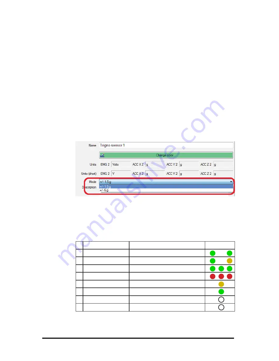
Each Trigno sensor can operate in one of 4 possible data collection 

modes, which determines the type of data being collected. When us-

ing EMGworks, the sensor mode can be chosen on the sensor settings 

pane. Note that the number of modes available is determined by the 

Trigno sensor type. 

Figure 37: 

Setting Sensor Modes in EMGworks.

Sensor States

There are 8 sensor states which are easily discernible by the behavior of 

the sensor’s on-board LED.

Status

LED Behavior

LED

1 Data Streaming

Green flash, 1Hz

2 Scanning

Amber/green, 1Hz

3 Pairing Successful

Green flash 3X, button pressed

4 Pairing Unsuccessful

Red flash, 3X, button pressed

5 Battery Charging

Amber solid, in cradle

6 Charging Complete

Green solid, in cradle

7 Charging Error

LED off, in cradle with power 

8 Sensor Off

LED off

Summary of Contents for Trigno PM-W02

Page 1: ...TrignoTM Personal Monitor User s Guide 1 TRIGNOTM Personal Monitor User s Guide PM W02 Copyright 2014 Delsys Incorporated Delsys Logo and EMGworks are Regis tered Trademarks of Delsys Inc MAN 014 1 5...

Page 2: ...ing the Personal Monitor 16 Turning the Personal Monitor ON OFF 17 User Interface and Navigation Buttons 17 Connecting the Personal Monitor to a Computer 18 Getting Started 19 Loading Protocols on the...

Page 3: ...3 Applying the Sensor Interface 33 Sensor Pairing 34 Sensor Factory Calibration 35 Smart Sensors 36 Sensor Modes 36 Sensor States 36 1 Data Streaming 37 2 Receiver Scanning 37 3 Sensor Pair Complete 3...

Page 4: ...the EMG and supporting signals by a qualified individual is required Rx ONLY DO NOT USE on Patients with implanted electronic devices of any kind including cardiac pace makers or similar assistive dev...

Page 5: ...al equipment while using Delsys EMG systems may result in burns at the site of the EMG sensor contacts Immediately discontinue device use if skin irritation or discomfort occurs Immediately discontinu...

Page 6: ...ts put forth by the Medical Device Di rective 93 42 EEC Class I device Annex VII Type BF device IEC 60601 1 Isolated device Class II IEC 60601 1 Do not dispose this product with house waste Contact De...

Page 7: ...sers the antenna type and its gain should be so chosen that the equivalent isotropi cally radiated power EIRP is not more than that required for suc cessful communication This equipment has been teste...

Page 8: ...YS INC makes no di agnosis or prescription by virtue of anything about this product System Requirements EMGworks 4 0 11 or later Windows 8 or Windows 7 32 or 64 bit x86 based operating sys tems Altern...

Page 9: ...his software for any purpose including commercial applications and to alter it and redistribute it freely subject to the following restrictions 1 The origin of this software must not be misrepresented...

Page 10: ...F accelerometer data which has 4 select able ranges 1 5g 4g 6g 9g Full triggering features further expand the possibility for integration with additional measurement technologies The Trigno Personal M...

Page 11: ...ce is connected with a USB port to a host com puter and sensor data are streamed into EMGworks for real time viewing and analysis to preview how a datalogger session will proceed and evaluate signal q...

Page 12: ...onitor System Components 1 Trigno Personal Monitor TPM Datalogger 2 Trigno Wireless Sensor 3 Trigno Desktop Base Recharge Station 4 Trigno Personal Monitor Medical Grade Recharger 5 Trigno Base Rechar...

Page 13: ...samples sec EMG baseline noise of 750 nV RMS CMRR 80dB 16 bit EMG signal resolution integrated 3DOF accelerometer 1 5 4 6 9g LED User feedback battery charge monitoring and status indicator environme...

Page 14: ...battery life usage dependent QVGA LCD display screen Automatic DAQ protocols Audio Visual prompts USB support for real time data viewing and memory download sensor status feedback charge status feedb...

Page 15: ...opriate plug adapter for your location Ensure that the Trigno sensors are properly fitted in the recharge pockets The sensor LEDs will illuminate to am ber during charging and green when charge is com...

Page 16: ...cting it to a PC Figure 7 Connecting the SC P07 power supply to the Personal Monitor for charging The TPM provides visual feedback to indicate the current battery level charging status and time until...

Page 17: ...n on upper left corner of the TPM for ap proximately 3 seconds or until the screen goes dark 2 Allow the Power down time as set in the device settings to elapse The device will only automatically shut...

Page 18: ...Select 1 2 3 Figure 11 TPM Navigation keys UP DOWN LEFT RIGHT SELECT and the three Softkeys Connecting the Personal Monitor to a Computer The TPM will charge when connected to any USB 2 0 compliant p...

Page 19: ...nning EMGworks in order to download the collected data Setup Protocol 1 Collect Data 2 Analyze Data 3 Figure 13 Using the Trigno Personal Monitor requires three basic steps 1 setup the desired data ac...

Page 20: ...e initialization is complete If your system was shipped with sensors these sensors are already paired to the Trigno Personal Monitor Otherwise it is necessary to first pair your existing sensors to th...

Page 21: ...lay a list of test protocols that have loaded onto the device Scroll through the list of protocols using the directional arrows and select the desired protocol using softkey 1 or the select button Fig...

Page 22: ...n indication of which sensors are being logged Pressing softkey 3 again Return will bring back the test status screen Status Connection Logging Data Battery Charge Channel No Signal Strength Figure 19...

Page 23: ...llected for each configuration Using the check boxes select those data files which you would like to download and select Close and Download Selected Data On a computer meeting the minimum system requi...

Page 24: ...dialog that appears or launch EMGworks Acquisition from the Start menu or desktop if this window does not present itself Figure 22 Connecting the TPM to a USB port Please wait a moment while the Trign...

Page 25: ...les Data files can be listed by selecting the Menu button on the home screen and then selecting View Data Files A listing of the all the stored data files on the device will be available These files a...

Page 26: ...Data files can be deleted from the device by using the navigation keys and selecting the Delete option softkey 1 from the Data Files View After selecting a file to delete the deletion confirmation scr...

Page 27: ...tion Following options are available Button Lock When engaged this feature will lock all buttons on the TPM during a test so that inadvertent button presses will have no effect on the device behavior...

Page 28: ...evel estimation Use the option only when directed to do so by Delsys Support Device Charging When set to OFF the device will not charge from the USB port This is useful when the device is connected to...

Page 29: ...e may be manually adjusted directly on the device Note It is recommended to set the PC where EMGworks is installed to use NTP network time protocol for clock synchronization to ensure an accurate devi...

Page 30: ...EMGworks and open or create a protocol that uses the TPM Click Retrieve Device Log from the A D Settings pane under the Hard ware node in the configuration tree You will be prompted to select a locati...

Page 31: ...e manually synchronized via a button click in EMGworks Hard Reset Note A hard reset of the device may cause internal memory cor ruption Consultation with Delsys technical support prior to initi ating...

Page 32: ...ice after the reformat is completed The PC hard drive is used as a temporary storage for data files and protocols from the device while the reformat is proceeding The reformat command can be accessed...

Page 33: ...d with the muscle fibers Align the sensor s arrow with the direction of the underlying muscle fibers Cleaning the Sensors Site Prior to affixing the EMG sensor on the surface of the skin the sensor si...

Page 34: ...use only Dis card after using Reseal storage bag to maintain freshness Do not use an Patients with allergies to silver Do not use on open wounds or injured or irritated skin Sensor Pairing Trigno sen...

Page 35: ...values in many cases without the need for a user initiated manual calibration After a pairing operation is completed the system automatically searches for pre existing factory calibration data on the...

Page 36: ...ble data collection modes which determines the type of data being collected When us ing EMGworks the sensor mode can be chosen on the sensor settings pane Note that the number of modes available is de...

Page 37: ...ate that the pairing opera tion between the sensor and the receiving unit has successfully been completed 4 Sensor Pair Incomplete Three successive red LED flashes indicate that the initiated pair com...

Page 38: ...ents electrically isolated from equip ment within their reach and since the PC running the Trigno Soft ware during data download and analysis is conceivably within their reach it too must be isolated...

Reviews: