Microprocessor Module
75
15
Microprocessor Module
Removing the Microprocessor Module
CAUTION:
Before you perform any of the procedures in this section, follow the safety instructions in the
Product Information Guide
.
NOTICE:
To avoid electrostatic discharge, ground yourself by using a wrist grounding strap or by periodically
touching an unpainted metal surface (such as the back panel) on the computer.
NOTICE:
Handle the microsprocessor module with care. Hold the microsprocessor module by its edges and
do not touch the processor die (the small chip in the center of the module).
1
Follow the instructions in "Preparing to Work Inside the Computer" on page 7.
2
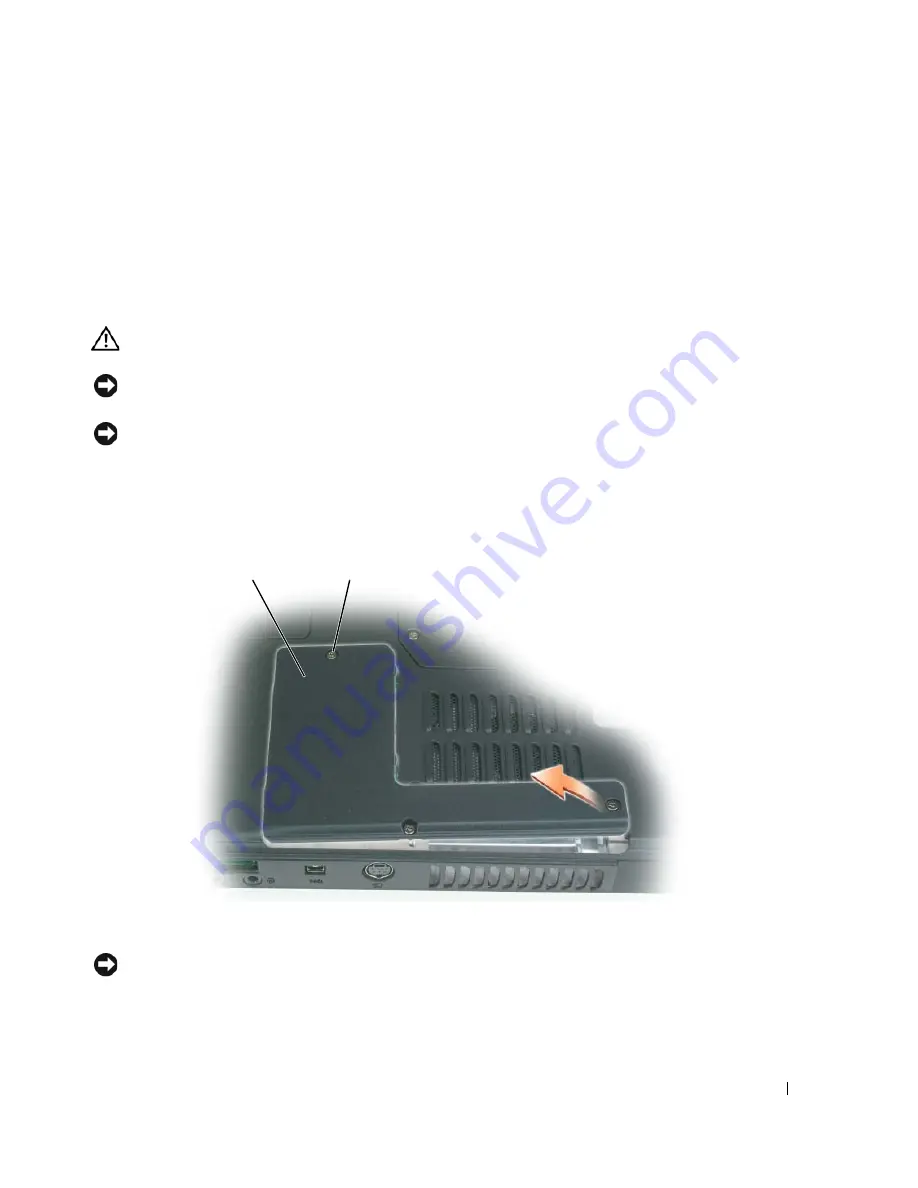
Loosen the three captive screws securing the microprocessor module cover, then remove the cover
and set it aside.
NOTICE:
To ensure maximum cooling for the microprocessor, do not touch the heat transfer areas on the
microprocessor thermal-cooling assembly. Oils in your skin can reduce the heat transfer capability of the
thermal pads.
1
microprocessor module cover
2
captive screws (3)
2
1
Summary of Contents for XPS M140
Page 12: ...12 Before You Begin ...
Page 14: ...14 System Components Exploded View of the Computer 1 2 3 4 10 5 6 7 13 9 12 11 8 ...
Page 16: ...16 System Components ...
Page 24: ...24 Hard Drive 1 hard drive in antistatic bag 2 foam packaging 1 2 ...
Page 28: ...28 Optical Drive ...
Page 40: ...40 Memory Module and Modem ...
Page 54: ...54 Wireless Mini PCI Card ...
Page 64: ...64 Display Assembly and Display Latch ...
Page 78: ...78 Microprocessor Module ...
Page 82: ...82 Speakers ...
Page 88: ...88 BIOS Updates ...
Page 91: ...Pin Assignments for I O Connectors 91 IEEE 1394 Connector Pin Signal 1 TPB 2 TPB 3 TPA 4 TPA ...


