58
Display Assembly and Display Latch
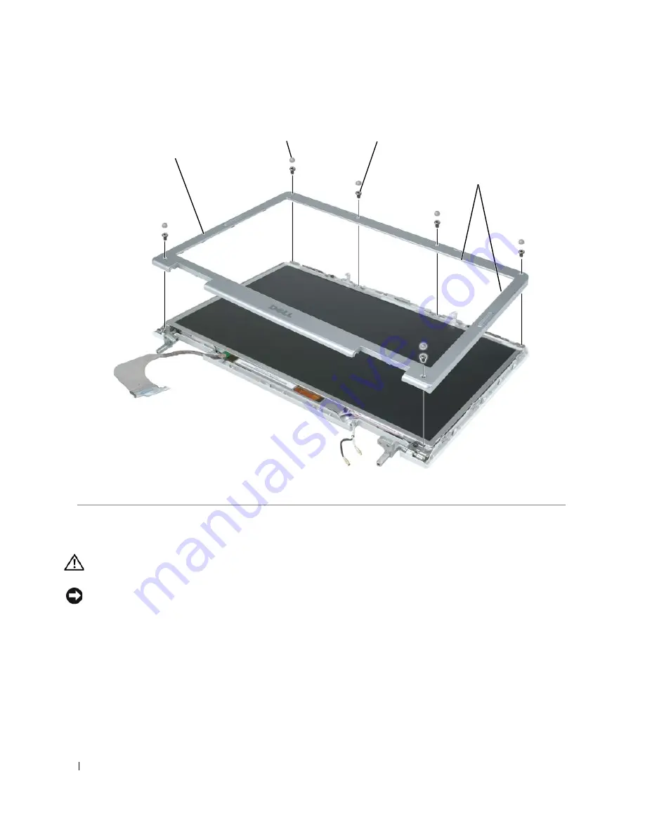
Replacing the Display Bezel
CAUTION:
Before you perform any of the procedures in this section, follow the safety instructions in the
Product
Information Guide
.
NOTICE:
To avoid electrostatic discharge, ground yourself by using a wrist grounding strap or by periodically
touching an unpainted metal surface (such as the back panel) on the computer.
1
Follow the instructions in "Preparing to Work Inside the Computer" on page 7
2
Follow the instructions in "Removing the Display Bezel" on page 57.
3
Starting near the hinges (near the Dell logo), use your fingers to snap the new bezel into place.
4
Replace the six M2.5 x 5-mm screws to secure the bezel.
5
Replace the six rubber bumpers to cover the screws.
6
Replace the display assembly (see "Replacing the Display Assembly" on page 56).
1
display bezel
2
rubber bumpers (6)
3
M2.5 x 5-mm
screws (6)
4
inside edge of bezel
1
2
3
4
Summary of Contents for XPS M140
Page 12: ...12 Before You Begin ...
Page 14: ...14 System Components Exploded View of the Computer 1 2 3 4 10 5 6 7 13 9 12 11 8 ...
Page 16: ...16 System Components ...
Page 24: ...24 Hard Drive 1 hard drive in antistatic bag 2 foam packaging 1 2 ...
Page 28: ...28 Optical Drive ...
Page 40: ...40 Memory Module and Modem ...
Page 54: ...54 Wireless Mini PCI Card ...
Page 64: ...64 Display Assembly and Display Latch ...
Page 78: ...78 Microprocessor Module ...
Page 82: ...82 Speakers ...
Page 88: ...88 BIOS Updates ...
Page 91: ...Pin Assignments for I O Connectors 91 IEEE 1394 Connector Pin Signal 1 TPB 2 TPB 3 TPA 4 TPA ...


