PowerConnect B-DCX-4S Backbone Hardware Reference Manual
81
53-1001808-01
RRP: PowerConnect B-DCX-4S chassis
5
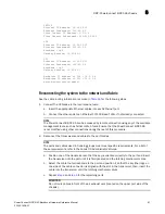
SWITCH
Ethernet IP Address: 10.32.50.12
Ethernet Subnetmask: 255.55.0.0
Fibre Channel IP Address: 1.2.3.4
Fibre Channel Subnetmask: 255.255.255.0
CP0
Ethernet IP Address: 10.32.50.10
Ethernet Subnetmask: 255.55.0.0
HostName : cp0
Gateway Address: 10.32.40.1
CP1
Ethernet IP Address: 10.32.50.11
Ethernet Subnetmask: 255.55.0.0
HostName : cp1
Gateway Address: 10.32.40.1
Backplane IP address of CP0 : 10.0.0.4
Backplane IP address of CP1 : 10.0.0.5
switch:admin>switch:admin>
Reconnecting the system to the network and fabric
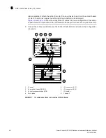
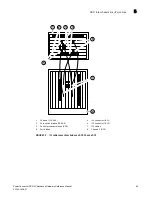
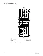
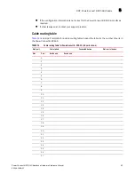
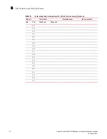
See the cable routing information recorded in
Table 14
for the following steps.
1. Connect the CP blades to the local area network:
a. Insert the appropriate Ethernet cables into each Ethernet port.
b. Connect the other ends to an Ethernet 10/100 Base-T LAN, if not already connected.
NOTE
The PowerConnect B-DCX-4S can be accessed by remote connection using any of the available
management tools, such as Telnet or Web Tools. Ensure that the PowerConnect B-DCX-4S
is not modified using other connections during the rest of this procedure.
2. Reconnect the transceivers and cables to the port blades:
NOTE
The ports and cables used in trunking groups must meet specific requirements. For a list of
these requirements, refer to the
Fabric OS Administrator’s Guide.
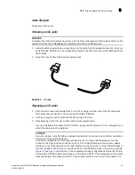
a. Position one of the transceivers so that the key is oriented correctly to the port and insert
the transceiver into the port until it is firmly seated and the latching mechanism clicks.
b. Select the cable that corresponds to the port and position it so that the key (the ridge on
one side of the cable connector) is aligned with the slot in the transceiver; then, insert the
cable into the transceiver until the latching mechanism clicks.
c. Repeat
step a
and
step b
for the remaining ports.
ATTENTION
Do not route cables in front of the air exhaust vent (located on the upper port side of the
chassis).

