


68
PowerConnect B-DCX-4S Backbone Hardware Reference Manual
53-1001808-01
RRP: Inter-chassis link (ICL) cables
5
also acceptable to attach the cables from slot 3 on one chassis to slot 3 on the second chassis
(or slot 6 to slot 6) as long as the left-to-right (top-to-bottom) rule is followed.
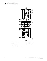
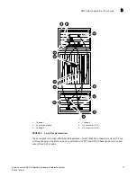
Figure 33
and
Figure 34
show the arrangement of cables in a 3-way configuration of backbone
chassis. Note the relationship of the horizontal DCX-4S layout to the vertical layout of the DCX.
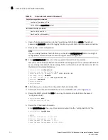
4. Once all the cables are attached, see the
Fabric OS Administrator’s Guide
for the configuration
procedure.
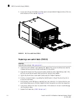
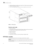
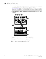
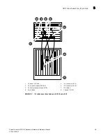
FIGURE 31
ICL cable connections – between two DCX-4S chassis
1
Chassis 1
5
ICL connector (ICL 1)
2
Core switch blades (CR4S-8)
6
ICL connector (ICL 0)
3
Control processor blades (CP8)
7
ICL cables
4
Port blades
8
Chassis 2
1
2
5
6
3
4
7
8


