background image

Drives: Dell OptiPlex 320 User's Guide

file:///N|/For_lekha/For%20Deepa/Nadia/UG/A00/en/nadia-temp-working-jul19/Nadia_UG_A00/Output/dt_drive.htm[5/22/2015 10:44:07 AM]

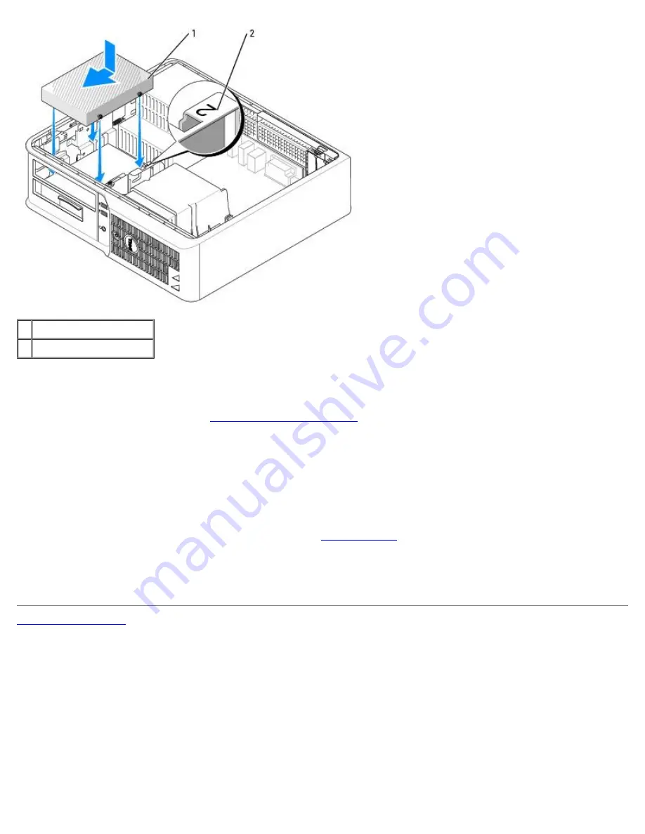
1 hard drive
2 slot verification number

7.  Replace the floppy drive and CD/DVD drive. 

8.  Check all connectors to ensure that they are properly cabled and firmly seated. 

9.  Replace the computer cover (see 

Replacing the Computer Cover

). 

10.  Insert bootable media into your boot drive. 

11.  Turn on the computer. 

12.  Partition and logically format your drive before you proceed to the next step. 

For instructions, see the documentation that came with your operating system.

13.  Test the hard drive by running the Dell Diagnostics (see 

Dell Diagnostics

). 

14.  Install your operating system on the hard drive. 

For instructions, see the documentation that came with your operating system.

Back to Contents Page


Summary of Contents for OptiPlex 320 DCNE

Page 1: ...Plex 320 User s Guide file N For_lekha For 20Deepa Nadia UG A00 en nadia temp working jul19 Nadia_UG_A00 Output index htm 5 22 2015 10 42 56 AM Dell OptiPlex 320 User s Guide Mini Tower Computer Desktop Computer ...

Page 2: ...oving the Computer Cover I O Panel Drives PCI and PCI Express Cards Power Supply Processor Battery System Board Memory Replacing the Computer Cover Notes Notices and Cautions NOTE A NOTE indicates important information that helps you make better use of your computer NOTICE A NOTICE indicates either potential damage to hardware or loss of data and tells you how to avoid the problem CAUTION A CAUTIO...

Page 3: ...ration Microsoft MS DOS and Windows are registered trademarks of Microsoft Corporation IBM is a registered trademark of International Business Machines Corporation Bluetooth is a trademark owned by Bluetooth SIG Inc and is used by Dell Inc under license ENERGY STAR is a registered trademark of the U S Environmental Protection Agency As an ENERGY STAR partner Dell Inc has determined that this produ...

Page 4: ...e or loss of data and tells you how to avoid the problem CAUTION A CAUTION indicates a potential for property damage personal injury or death Abbreviations and Acronyms For a complete list of abbreviations and acronyms see the Glossary If you purchased a Dell n Series computer any references in this document to Microsoft Windows operating systems are not applicable Information in this document is ...

Page 5: ...ction Agency As an ENERGY STAR partner Dell Inc has determined that this product meets the ENERGY STAR guidelines for energy efficiency Other trademarks and trade names may be used in this document to refer to either the entities claiming the marks and names or their products Dell Inc disclaims any proprietary interest in trademarks and trade names other than its own Models DCSM and DCNE June 2006...

Page 6: ...ities CD also known as ResourceCD NOTE The Drivers and Utilities CD may be optional and may not ship with your computer Documentation and drivers are already installed on your computer You can use the CD to reinstall drivers see Reinstalling Drivers and Utilities to run the Dell Diagnostics see Dell Diagnostics or to access your documentation Readme files may be included on your CD to provide last...

Page 7: ...th other Dell customers Upgrades Upgrade information for components such as memory the hard drive and the operating system Customer Care Contact information service call and order status warranty and repair information Service and support Service call status and support history service contract online discussions with technical support Reference Computer documentation details on my computer config...

Page 8: ...ribes your problem and click the arrow icon 3 Click the topic that describes your problem 4 Follow the instructions on the screen How to reinstall my operating system Operating System CD NOTE The Operating System CD may be optional and may not ship with your computer The operating system is already installed on your computer To reinstall your operating system use the Operating System CD See Reinst...

Page 9: ...age Mini Tower Computer Dell OptiPlex 320 User s Guide About Your Mini Tower Computer Inside Your Computer About Your Mini Tower Computer Front View 1 location of Service Tag Use the Service Tag to identify your computer when you access the Dell Support website or call technical support 2 CD DVD drive Insert a CD or DVD if supported into this drive 3 floppy Insert a floppy disk into this drive ...

Page 10: ...ton to turn on the computer NOTICE To avoid losing data do not turn off the computer by pressing the power button Instead perform an operating system shutdown NOTICE If your operating system has ACPI enabled when you press the power button the computer will perform an operating system shutdown 8 power light The power light illuminates and blinks or remains solid to indicate different operating sta...

Page 11: ...elector do not have a voltage selection switch on the back panel of the computer and can automatically detect the correct operating voltage To help avoid damaging a computer with a manual voltage selection switch set the switch for the voltage that most closely matches the AC power available in your location NOTICE The voltage selection switch must be set to the 115 V position even though the AC p...

Page 12: ...attached NOTE Do not plug a telephone cable into the network connector On computers with a network adapter card use the connector on the card It is recommended that you use Category 5 wiring and connectors for your network If you must use Category 3 wiring force the network speed to 10 Mbps to ensure reliable operation 4 network activity light This light flashes yellow when the computer is transmi...

Page 13: ...ort The default designation is COM1 for serial connector 1 For more information see System Setup Options Inside Your Computer CAUTION Before you begin any of the procedures in this section follow the safety instructions located in the Product Information Guide CAUTION To avoid electrical shock always unplug your computer from the electrical outlet before removing the computer cover NOTICE Be caref...

Page 14: ...SWD 11 internal buzzer SPKR1 3 processor connector CPU 12 RTC reset jumper RTCRST 4 processor power connector 12VPOWER 13 battery socket BATT 5 front panel connector FNT_PANEL 14 PCI Express x16 card connector 6 memory module connectors DIMM_1 DIMM_2 15 PCI card connectors 2 7 SATA drive connectors SATA0 SATA1 16 floppy drive connector FLOPPY 8 power connector POWER 17 serial PS 2 connector PS2 SE...

Page 15: ...ory connectors two Memory modules supported 256 MB 512 MB or 1 GB non ECC Minimum memory 256 MB Maximum memory 4 GB BIOS address F0000h Computer Information Chipset ATI Radeon Xpress 200 Professional Data bus width 64 bits Address bus width 32 bits DMA channels eight Interrupt levels 24 BIOS chip NVRAM 4 Mb NIC integrated network interface capable of 10 100 communication Green A good connection ex...

Page 16: ...0 Mbps Cards full height cards supported PCI connectors two connector size 120 pins connector data width maximum 32 bits PCI Express connectors one x16 power 25 W maximum connector size 164 pins connector data width maximum sixteen PCI Express lane Drives Externally accessible one 3 5 inch drive bay two 5 25 inch drive bays Internally accessible two bays for 1 inch high hard drives Connectors Exte...

Page 17: ...ified by the remote boot environment PXE rather than from one of the devices in the system setup Boot Sequence option during system tart up only F12 or Ctrl Alt F8 displays a boot device menu that allows the user to enter a device for a single boot during system start up only as well as options to run hard drive and system diagnostics Controls and Lights Power control push button Power light green...

Page 18: ... cm 16 3 inches Width 18 5 cm 7 3 inches Depth 43 9 cm 17 3 inches Weight 12 34 kg 27 2 lb Environmental Temperature Operating 10 to 35 C 50 to 95 F Storage 40 to 65 C 40 to 149 F Relative humidity 20 to 80 noncondensing Maximum vibration Operating 5 to 350 Hz at 0 0002 G2 Hz Storage 5 to 500 Hz at 0 001 to 0 01 G2 Hz Maximum shock Operating 45 G 5 with pulse duration of 2 msec 10 equivalent to 20...

Page 19: ...t configures manages and monitors computers and other devices on a corporate network IT Assistant manages assets configurations events alerts and security for computers equipped with industry standard management software It supports instrumentation that conforms to SNMP DMI and CIM industry standards Dell OpenManage Client instrumentation which is based on DMI and CIM is available for your compute...

Page 20: ... it is your responsibility to obtain and use additional forms of protection such as data encryption programs System Password NOTICE If you leave your computer running and unattended without having a system password assigned or if you leave your computer unlocked so that someone can disable the password by changing a jumper setting anyone can access the data stored on your hard drive Option Setting...

Page 21: ...ssword Status is set to Unlocked Type in the password and press ENTER to leave password security enabled press CTRL ENTER to disable password security Enter password If Password Status is set to Locked Type the password and press Enter If you have assigned an administrator password the computer accepts your administrator password as an alternate system password If you type a wrong or incomplete sy...

Page 22: ...assword jumper on the system board is in the enabled position the default setting Assigning an Administrator Password The administrator password can be the same as the system password NOTE If the two passwords are different the administrator password can be used as an alternate system password However the system password cannot be used in place of the administrator password 1 Enter system setup an...

Page 23: ...n Administrator Password 4 Exit system setup Disabling a Forgotten Password and Setting a New Password To reset system and or administrator passwords see Clearing Forgotten Passwords System Setup Overview Use system setup as follows To change the system configuration information after you add change or remove any hardware in your computer To set or change a user selectable option such as the user ...

Page 24: ...d in this section may or may not appear System System Info Lists the computer name BIOS Version Service Tag Express Service Code if applicable and the Asset Tag None of these fields can be modified Processor Info Identifies the CPU type bus speed clock speed and L2 cache size States whether the processor is Hyper Threading and multiple core capable and whether it supports 64 bit technology Memory ...

Page 25: ...rectional protocol NOTE If you set the LPT Port Mode to ECP the LPT Port DMA appears in the option menu LPT Port Address Determines the address that the built in parallel port uses Serial Port 1 Auto default Determines how the serial port operates Auto the default setting automatically configures a connector to a particular designation COM1 or COM3 Serial Port 2 Auto default Determines how the ser...

Page 26: ...d allows a new hard drive password to be assigned and verified Password Changes Unlocked default Determines the interaction between the System password and the Admin password Locked prevents a user without a valid Admin password from being able to modify the System password Unlocked allows a user with a valid System password to modify the system password Execute Disable On default Enables or disab...

Page 27: ...y steps Off does not skip any steps during computer startup On starts the system more quickly Numlock Key On default Determines the functionality of the numeric keys on the right side of your keyboard Off commands the right keypad keys to function as arrows On commands the right keypad keys to function as numbers POST Hotkeys Determines whether the sign on screen displays a message stating the key...

Page 28: ...r 3 When F2 Setup F12 Boot Menu appears in the upper right corner of the screen press F12 If you wait too long and the operating system logo appears continue to wait until you see the Microsoft Windows desktop Then shut down your computer and try again see Turning Off Your Computer The Boot Device Menu appears listing all available boot devices Each device has a number next to it 4 At the bottom o...

Page 29: ... next to the USB device The computer boots to the USB device Floppy Drive 1 In system setup set the Diskette Drive option to USB 2 Save and exit system setup 3 Connect the USB floppy drive insert a bootable floppy and re boot the system Clearing Forgotten Passwords CAUTION Before you begin any of the procedures in this section follow the safety instructions located in the Product Information Guide...

Page 30: ... computer and monitor to electrical outlets and turn them on 5 After the Microsoft Windows desktop appears on your computer shut down your computer see Turning Off Your Computer 6 Turn off the monitor and disconnect it from the electrical outlet 7 Disconnect the computer power cable from the electrical outlet and press the power button to ground the system board 8 Remove the computer cover 9 Locat...

Page 31: ...the computer stand if used NOTICE To connect a network cable first plug the cable into the network wall jack and then plug it into the computer 5 Connect your computer and devices to electrical outlets and turn them on Hyper Threading Hyper Threading is an Intel technology that can enhance overall computer performance by allowing one physical processor to function as two logical processors capable...

Page 32: ...moving system power Waking up from this mode restarts the computer and the memory contents are restored Operation then resumes where the computer left off when it entered the hibernation mode Shutdown This sleep mode removes all power from the computer except a small auxiliary amount As long as the computer remains connected to an electrical outlet it can be automatically or remotely started For e...

Page 33: ...for the monitor s antistatic coating Wipe the keyboard computer and plastic part of the monitor with a soft cleaning cloth moistened with a solution of three parts water and one part dish washing detergent Do not soak the cloth or let water drip inside your computer or keyboard Mouse If your screen cursor skips or moves abnormally clean the mouse To clean a non optical mouse 1 Turn the retainer ri...

Page 34: ...CDs or DVDs try cleaning the discs 1 Hold the disc by its outer edge You can also touch the inside edge of the center hole NOTICE To prevent damaging the surface do not wipe in a circular motion around the disc 2 With a soft lint free cloth gently wipe the bottom of the disc the unlabeled side in a straight line from the center to the outer edge of the disc For stubborn dirt try using water or a d...

Page 35: ...deo cable which is available at most consumer electronics stores An S video cable is not included with your computer You may connect only one monitor VGA or DVI in addition to the television See the documentation that came with your TV to ensure that you properly configure and connect the TV Connecting Two to Three Monitors Using Surround View NOTE These steps only apply to a computer with an ATI ...

Page 36: ...the TV OUT connector on the graphics card in the back of the computer and the other to the S video input connector on your television Changing the Display Settings 1 After you connect the monitor s or television turn on the computer The Microsoft Windows desktop displays on the primary monitor 2 Enable clone mode or extended desktop mode in the display settings In clone mode both monitors display ...

Page 37: ...A driver acts like a translator between the device and any other programs that use the device Each device has its own set of specialized commands that only its driver recognizes Dell ships your computer to you with required drivers already installed no further installation or configuration is needed NOTICE The optional Drivers and Utilities CD Resource CD may contain drivers for operating systems ...

Page 38: ...the new driver was installed and click Properties 7 Click the Drivers tab 8 Click Roll Back Driver If Device Driver Rollback does not resolve the problem then use System Restore see Enabling System Restore to return your computer to the operating state that existed before you installed the new driver Using the Optional Drivers and Utilities CD If using Device Driver Rollback or System Restore see ...

Page 39: ...r recover them Creating a Restore Point 1 Click the Start button and click Help and Support 2 Click System Restore 3 Follow the instructions on the screen Restoring the Computer to an Earlier Operating State NOTICE Before you restore the computer to an earlier operating state save and close any open files and exit any open programs Do not alter open or delete any files or programs until the system...

Page 40: ...e System Restore tab 5 Ensure that Turn off System Restore is unchecked Reinstalling Microsoft Windows XP NOTICE You must use Windows XP Service Pack 1 or later when you reinstall your operating system Before You Begin If you are considering reinstalling the Windows XP operating system to correct a problem with a newly installed driver first try using Windows XP Device Driver Rollback see Using Wi...

Page 41: ...s to select CD ROM and press Enter 6 When the Press any key to boot from CD message appears press any key Windows XP Setup 1 When the Windows XP Setup screen appears press Enter to select To set up Windows now 2 Read the information on the Microsoft Windows Licensing Agreement screen and press F8 to accept the license agreement 3 If your computer already has Windows XP installed and you want to re...

Page 42: ...g message appears Press any key to boot from the CD 13 When the Welcome to Microsoft screen appears click Next 14 When the How will this computer connect to the Internet message appears click Skip 15 When the Ready to register with Microsoft screen appears select No not at this time and click Next 16 When the Who will use this computer screen appears you can enter up to five users 17 Click Next 18...

Page 43: ... s instructions CAUTION Before you begin any of the procedures in this section follow the safety instructions located in the Product Information Guide Replace the battery If you have to repeatedly reset time and date information after turning on the computer or if an incorrect time or date displays during start up replace the battery see Battery If the battery still does not work properly contact ...

Page 44: ... If the stream is interrupted an error occurs Try closing all programs before you write to the CD DVD RW Turn off Standby mode in Windows before writing to a CD DVD RW disc See Power Management Hard drive problems Running the Dell IDE Hard Drive Diagnostics The Dell IDE Hard Drive Diagnostics is a utility that tests the hard drive to troubleshoot or confirm a hard drive failure 1 Turn on your comp...

Page 45: ...efore you begin any of the procedures in this section follow the safety instructions located in the Product Information Guide NOTE If you installed a unique image on your computer or if you had to reinstall your operating system run the DSS utility DSS is available on your Drivers and Utilities CD see Finding Information and at support dell com NOTE You must use Microsoft Windows XP Service Pack 1...

Page 46: ...the operating system installed on your computer Ensure that your computer meets the minimum hardware requirements needed to run the software See the software documentation for information Ensure that the program is installed and configured properly Verify that the device drivers do not conflict with the program If necessary uninstall and then reinstall the program Back up your files immediately Us...

Page 47: ... Guide Check the mouse cable 1 Check the cable connector for bent or broken pins and for damaged or frayed cables Straighten bent pins 2 Remove mouse extension cables if used and connect the mouse directly to the computer 3 Shut down the computer reconnect the mouse cable as shown in the Quick Reference Guide for your computer and then restart the computer Restart the computer 1 Simultaneously pre...

Page 48: ...blems Fill out the Diagnostics Checklist as you complete these checks CAUTION Before you begin any of the procedures in this section follow the safety instructions located in the Product Information Guide If the power light is green and the computer is not responding See Diagnostic Lights If the power light is blinking green The computer is in standby mode Press a key on the keyboard or move the m...

Page 49: ...r contact the printer s manufacturer Check the printer documentation See the printer documentation for setup and troubleshooting information Ensure that the printer is turned on Check the printer cable connections See the printer documentation for cable connection information Ensure that the printer cables are securely connected to the printer and the computer Test the electrical outlet Ensure tha...

Page 50: ...ics See Dell Diagnostics Sound and Speaker Problems Fill out the Diagnostics Checklist as you complete these checks CAUTION Before you begin any of the procedures in this section follow the safety instructions located in the Product Information Guide No sound from speakers NOTE The volume control in some MP3 players overrides the Windows volume setting If you have been listening to MP3 songs ensur...

Page 51: ...l Diagnostics Check for software and hardware conflicts See Resolving Software and Hardware Incompatibilities No sound from headphones Check the headphone cable connection Ensure that the headphone cable is securely inserted into the headphone connector Disable digital mode Your headphones do not work if the CD drive is operating in digital mode 1 Click the Start button click Control Panel and the...

Page 52: ...mp Test the monitor Connect a properly working monitor to the computer and try using the monitor If the new monitor works the original monitor is faulty Check the diagnostic lights See Diagnostic Lights Check the card setting Enter system setup and ensure that Primary Video option is set correctly Exit system setup and restart your computer see System Setup Run the monitor self test Check the moni...

Page 53: ...essories System Tools and then click Files and Settings Transfer Wizard 2 When the Files and Settings Transfer Wizard welcome screen appears click Next 3 On the Which computer is this screen click New Computer and click Next 4 On the Do you have a Windows XP CD screen click I will use the wizard from the Windows XP CD and click Next 5 When the Now go to your old computer screen appears go to your ...

Page 54: ...an account type click one of the following options Computer administrator You can change all computer settings Limited You can change only your own personal settings such as your password You cannot install programs or use the Internet NOTE Additional options may be available depending on whether you are using Windows XP Home Edition or Windows XP Professional Also options available in Windows XP ...

Page 55: ...with a telephone wall jack 2 Connect the other end of the network cable to a network connection device such as a network wall jack Network Setup Wizard The Microsoft Windows XP operating system provides a Network Setup Wizard to guide you through the process of sharing files printers or an Internet connection between computers in a home or small office 1 Click the Start button point to All Program...

Page 56: ...orks only on Dell computers Enter system setup review your computer s configuration information and ensure that the device you want to test displays in system setup and is active see System Setup Start the Dell Diagnostics from either your hard drive or from the Drivers and Utilities CD an optional CD also known as the ResourceCD See Dell Diagnostics Starting the Dell Diagnostics From Your Hard Dr...

Page 57: ...e Dell Diagnostics Dell Diagnostics Main Menu 1 After the Dell Diagnostics loads and the Main Menu screen appears click the button for the option you want Option Function Express Test Performs a quick test of devices This test typically takes 10 to 20 minutes and requires no interaction on your part Run Express Test first to increase the possibility of tracing the problem quickly Extended Test Per...

Page 58: ... action is required Blinking green The computer is in a power saving mode Microsoft Windows XP Press the power button move the mouse or press a key on the keyboard to wake the computer Blinks green several times and then turns off A configuration error exists Check the diagnostic lights to see if the specific problem is identified see Diagnostic Lights Solid yellow The Dell Diagnostics is running ...

Page 59: ...art the computer Memory modules are detected but a memory failure has occurred If you have one memory module installed reinstall it and restart the computer see Memory for instructions on how to remove and install memory modules If you have two or more memory modules installed remove the modules reinstall one module and then restart the computer If the computer starts normally reinstall an additio...

Page 60: ...g off to indicate normal operating condition None Beep Codes Your computer might emit a series of beeps during start up if the monitor cannot display errors or problems This series of beeps called a beep code identifies a problem One possible beep code code 1 3 1 consists of one beep a burst of three beeps and then one beep This beep code tells you that the computer encountered a memory problem If...

Page 61: ...ct Information Guide If the message is not listed see the documentation for the operating system or the program that was running when the message appeared A filename cannot contain any of the following characters Do not use these characters in filenames A required DLL file was not found The program that you are trying to open is missing an essential file To remove and then reinstall the program 1 ...

Page 62: ...he drive Gate A20 failure See Lockups and Software Problems Hard disk configuration error Hard disk controller failure Hard disk drive failure Hard disk drive failure See Drive Problems Insert bootable media Insert a bootable floppy disk or CD Invalid configuration information please run SETUP program Enter system setup and correct the computer configuration information see System Setup Keyboard f...

Page 63: ...correct see System Setup No timer tick interrupt Run the Dell Diagnostics See Dell Diagnostics Non system disk or disk error Replace the floppy disk with one that has a bootable operating system or remove the floppy disk from drive A and restart the computer Not a boot diskette Insert a bootable floppy disk and restart your computer Not enough memory or resources Close some programs and try again ...

Page 64: ...EIDE controller is operating outside of normal specifications It is advisable to immediately back up your data and replace your hard drive by calling your support desk or Dell If no replacement drive is immediately available and the drive is not the only bootable drive enter system setup and change the appropriate drive setting to None see System Setup Then remove the drive from the computer Write...

Page 65: ...perties window reports the devices that need to be re configured 6 Reconfigure the devices or remove the devices from the Device Manager See the documentation that came with the device for information on configuring the device To resolve incompatibilities using the Windows XP Hardware Troubleshooter 1 Click the Start button and click Help and Support 2 Type hardware troubleshooter in the Search fi...

Page 66: ... not resolved the problem contact Dell NOTE Call technical support from a telephone near or at the computer so that technical support can assist you with any necessary procedures NOTE Dell s Express Service Code system may not be available in all countries When prompted by Dell s automated telephone system enter your Express Service Code to route the call directly to the proper support personnel I...

Page 67: ...rs about their portable and desktop computers When you call AutoTech use your touch tone telephone to select the subjects that correspond to your questions The AutoTech service is available 24 hours a day 7 days a week You can also access this service through the technical support service For the telephone number to call see the contact numbers for your region in Contacting Dell Automated Order St...

Page 68: ...py of the Diagnostics Checklist indicating the tests you have run and any error messages reported by the Dell Diagnostics 4 Include any accessories that belong with the item s being returned power cables software floppy disks guides and so on if the return is for credit 5 Pack the equipment to be returned in the original or equivalent packing materials You are responsible for paying shipping expen...

Page 69: ...find the appropriate country section in the table below NOTE Toll free numbers are for use within the country for which they are listed NOTE In certain countries support specific to Dell XPS computers is available at a separate telephone number listed for participating countries If you do not see a telephone number listed that is specific for XPS computers you may contact Dell through the support ...

Page 70: ...upport 13DELL 133355 Austria Vienna International Access Code 900 Country Code 43 City Code 1 Website support euro dell com E mail tech_support_central_europe dell com Home Small Business Sales 0820 240 530 00 Home Small Business Fax 0820 240 530 49 Home Small Business Customer Care 0820 240 530 14 Preferred Accounts Corporate Customer Care 0820 240 530 16 Support for XPS 0820 240 530 81 Home Smal...

Page 71: ...ree 1 800 247 9362 Customer Service Home Sales Small Business toll free 1 800 847 4096 Customer Service med large business government toll free 1 800 326 9463 Customer Service printers projectors televisions handhelds digital jukebox and wireless toll free 1 800 847 4096 Hardware Warranty Support Home Sales Small Business toll free 1 800 906 3355 Hardware Warranty Support med large bus government ...

Page 72: ... Corporate Accounts East Government and Education toll free 800 858 2669 Large Corporate Accounts Queue Team toll free 800 858 2572 Large Corporate Accounts South toll free 800 858 2355 Large Corporate Accounts West toll free 800 858 2811 Large Corporate Accounts Spare Parts toll free 800 858 2621 Colombia Website www dell com cl E mail la techsupport dell com General Support 01 800 915 4755 Costa...

Page 73: ...pport 800 6132 Finland Helsinki International Access Code 990 Country Code 358 City Code 9 Website support euro dell com E mail fi_support dell com Technical Support 0207 533 555 Customer Care 0207 533 538 Switchboard 0207 533 533 Sales under 500 employees 0207 533 540 Fax 0207 533 530 Sales over 500 employees 0207 533 533 Fax 0207 533 530 France Paris Montpellier International Access Code 00 Coun...

Page 74: ...Gold Service Switchboard 2108129811 Sales 2108129800 Fax 2108129812 Grenada E mail la techsupport dell com General Support toll free 1 866 540 3355 Guatemala E mail la techsupport dell com General Support 1 800 999 0136 Guyana E mail la techsupport dell com General Support toll free 1 877 270 4609 Hong Kong International Access Code 001 Country Code 852 Website support ap dell com Technical Suppor...

Page 75: ... K Sales dial within U K only 0870 907 4000 Italy Milan International Access Code 00 Country Code 39 City Code 02 Website support euro dell com Home and Small Business Technical Support 02 577 826 90 Customer Care 02 696 821 14 Fax 02 696 821 13 Switchboard 02 696 821 12 Corporate Technical Support 02 577 826 90 Customer Care 02 577 825 55 Fax 02 575 035 30 Switchboard 02 577 821 Jamaica E mail la...

Page 76: ...600 Fax 2194 6202 Switchboard 2194 6000 Latin America Customer Technical Support Austin Texas U S A 512 728 4093 Customer Service Austin Texas U S A 512 728 3619 Fax Technical Support and Customer Service Austin Texas U S A 512 728 3883 Sales Austin Texas U S A 512 728 4397 SalesFax Austin Texas U S A 512 728 4600 or 512 728 3772 Luxembourg International Access Code 00 Country Code 352 Website sup...

Page 77: ...r XPS 020 674 45 94 Technical Support for all other Dell computers 020 674 45 00 Technical Support Fax 020 674 47 66 Home Small Business Customer Care 020 674 42 00 Relational Customer Care 020 674 4325 Home Small Business Sales 020 674 55 00 Relational Sales 020 674 50 00 Home Small Business Sales Fax 020 674 47 75 Relational Sales Fax 020 674 47 50 Switchboard 020 674 50 00 Switchboard Fax 020 6...

Page 78: ...neral Support 1 877 537 3355 St Kitts and Nevis Website www dell com kn E mail la techsupport dell com General Support toll free 1 866 540 3355 St Lucia Website www dell com lc E mail la techsupport dell com General Support 1 800 882 1521 St Vincent and the Grenadines Website www dell com vc E mail la techsupport dell com General Support toll free 1 877 441 4740 Singapore Singapore International A...

Page 79: ...Code 34 City Code 91 Website support euro dell com Home and Small Business Technical Support 902 100 130 Customer Care 902 118 540 Sales 902 118 541 Switchboard 902 118 541 Fax 902 118 539 Corporate Technical Support 902 100 130 Customer Care 902 115 236 Switchboard 91 722 92 00 Fax 91 722 95 83 Sweden Upplands Vasby International Access Code 00 Country Code 46 City Code 8 Website support euro del...

Page 80: ...free 1800 0060 07 Technical Support PowerApp PowerEdge PowerConnect and PowerVault toll free 1800 0600 09 Customer Care toll free 1800 006 007 option 7 Corporate Sales toll free 1800 006 009 Transaction Sales toll free 1800 006 006 Trinidad Tobago Website www dell com tt E mail la techsupport dell com General Support 1 800 805 8035 Turks and Caicos Islands Website www dell com tc E mail la techsup...

Page 81: ...mer Service toll free 1 800 624 9897 Employee Purchase Program EPP Customers toll free 1 800 695 8133 Financial Services website www dellfinancialservices com Financial Services lease loans toll free 1 877 577 3355 Financial Services Dell Preferred Accounts DPA toll free 1 800 283 2210 Business Customer Service and Support toll free 1 800 456 3355 Employee Purchase Program EPP Customers toll free ...

Page 82: ...0 User s Guide file N For_lekha For 20Deepa Nadia UG A00 en nadia temp working jul19 Nadia_UG_A00 Output gethelp htm 5 22 2015 10 43 23 AM Venezuela E mail la techsupport dell com General Support 0800 100 4752 Back to Contents Page ...

Page 83: ... Page Warranty Dell OptiPlex 320 User s Guide Dell Inc Dell manufactures its hardware products from parts and components that are new or equivalent to new in accordance with industry standard practices For information about the Dell warranty for your computer see the Product Information Guide or separate paper warranty document that shipped with your computer Back to Contents Page ...

Page 84: ...pment These limits are designed to provide reasonable protection against harmful interference in a residential installation However there is no guarantee that interference will not occur in a particular installation If this equipment does cause harmful interference with radio or television reception which can be determined by turning the equipment off and on you are encouraged to try to correct th...

Page 85: ...e procedures in this document may require the following tools Small flat blade screwdriver Phillips screwdriver Long Phillips screwdriver Flash BIOS update program floppy disk or CD Turning Off Your Computer NOTICE To avoid losing data save and close any open files and exit any open programs before you turn off your computer 1 Shut down the operating system a Save and close any open files exit any...

Page 86: ...t keep them evenly aligned to avoid bending any connector pins Also before you connect a cable ensure that both connectors are correctly oriented and aligned To avoid damaging the computer perform the following steps before you begin working inside the computer 1 Turn off your computer NOTICE To disconnect a network cable first unplug the cable from your computer and then unplug it from the networ...

Page 87: ...ide CAUTION To guard against electrical shock always unplug your computer from the electrical outlet before removing the computer cover 1 Follow the procedures in Before You Begin 2 If you have installed a padlock through the padlock ring on the back panel remove the padlock 3 Lay the computer on its side 4 Slide the cover release latch back as you lift the cover 5 Grip the sides of the computer c...

Page 88: ...the Computer Cover Dell OptiPlex 320 User s Guide file N For_lekha For 20Deepa Nadia UG A00 en nadia temp working jul19 Nadia_UG_A00 Output mt_remov htm 5 22 2015 10 43 29 AM 3 padlock ring Back to Contents Page ...

Page 89: ... from the electrical outlet before removing the cover NOTE Note the routing of all cables as you remove them so that you can re route them correctly when installing the new I O panel 1 Follow the procedures in Before You Begin NOTICE When sliding the I O panel out of the computer be extremely careful Carelessness my result in damage to the cable connectors and the cable routing clips 2 Remove the ...

Page 90: ...pan htm 5 22 2015 10 43 31 AM 3 I O panel 4 I O cable connector Replacing the I O Panel 1 To replace the I O panel follow the removal procedure in the reverse order NOTE Use the guides on the I O panel bracket to help position the I O panel in place and use the notch on the I O panel bracket to help seat the panel Back to Contents Page ...

Page 91: ...e General Installation Guidelines Hard Drive Drive Panel Inserts Floppy Drive CD DVD Drive Your computer supports Up to two SATA serial ATA hard drives One optional floppy drive Up to two CD or DVD drives NOTE Due to the limited number of drive bays and IDE controllers on this computer you will not be able to connect all supported devices at once 1 CD DVD drive 2 floppy drive 3 hard drive General ...

Page 92: ... board Connect SATA CD DVD drives to the connector labeled SATA2 or SATA3 SATA hard drives should be connected to the connectors labeled SATA0 or SATA1 on the system board To locate system board connectors see System Board Components IDE Drive Addressing When you connect two IDE devices to a single IDE data cable and configure them for the cable select setting the device attached to the last conne...

Page 93: ...sconnecting a SATA data cable hold the cable by the black connector at each end NOTICE When you connect an IDE data cable do not place the colored stripe away from pin 1 of the connector Reversing the cable prevents the drive from operating and could damage the controller the drive or both Hard Drive CAUTION Before you begin any of the procedures in this section follow the safety instructions in t...

Page 94: ...temp working jul19 Nadia_UG_A00 Output mt_drive htm 5 22 2015 10 43 38 AM 1 hard drive data cable 2 hard drive data connector on system board 3 power cable 5 Press the blue release tabs on each side of the drive towards each other and slide the drive up and out of the computer 1 hard drive ...

Page 95: ...drive and prepare it for installation 2 Check the documentation for the drive to verify that it is configured for your computer 3 If your replacement hard drive does not have the plastic hard drive bracket attached remove the bracket from the existing drive by unsnapping it from the drive Snap the bracket onto the new drive 1 hard drive 2 hard drive bracket 4 Gently slide the hard drive into the d...

Page 96: ..._drive htm 5 22 2015 10 43 38 AM 5 Connect the power and data cables to the drive 1 hard drive data cable 2 hard drive data connector on system board 3 power cable 6 Ensure that the data cable is securely connected to the connector on the system board 7 Check all connectors to ensure that they are properly cabled and firmly seated ...

Page 97: ...the primary drive install your operating system on the hard drive Adding a Second Hard Drive CAUTION Before you begin any of the procedures in this section follow the safety instructions in the Product Information Guide CAUTION To guard against electrical shock always unplug your computer from the electrical outlet before removing the computer cover NOTICE To avoid damage to the drive do not set i...

Page 98: ...ess in on the blue release tabs on each side of the drive and slide the first hard drive up and out of the upper bay c Gently slide the first hard drive into the lower bay until it clicks into place 6 Gently slide the new hard drive into the upper bay until it clicks into place 7 Connect a power cable to each drive 8 Attach the SATA data cable removed in step 5 to the first hard drive 9 Locate an ...

Page 99: ...8 AM 1 hard drive data cable 2 hard drive data connector on system board SATA0 or SATA1 3 power cable 10 Replace the computer cover see Replacing the Computer Cover Drive Panel Inserts 1 Follow the procedures in Before You Begin 2 Remove the drive panel by sliding the drive release latch downward to open the panel Then remove the drive panel from the hinges ...

Page 100: ... 43 38 AM 1 drive panel 2 release tab 3 drive panel insert 3 Find the drive panel insert in front of the drive bay that you want to use 4 Gently press the release tab of the insert to remove it from the drive panel 1 CD DVD drive panel insert 2 floppy drive panel insert 3 holder for shoulder screws 5 Reattach the drive panel to the front of the computer ...

Page 101: ...t Information Guide CAUTION To guard against electrical shock always unplug your computer from the electrical outlet before removing the computer cover Removing the Floppy Drive 1 Follow the procedures in Before You Begin 2 Remove the drive panel by sliding the drive release latch downward to open the panel and then remove it from the hinges 3 Disconnect the power and data cables from the back of ...

Page 102: ...the computer cover see Replacing the Computer Cover Installing the Floppy Drive 1 If you are replacing a floppy drive remove the shoulder screws from the existing drive and attach the screws to the replacement drive 2 If you are installing a new floppy drive a Remove the drive panel insert for your new drive see Drive Panel Inserts b Remove the shoulder screws from the inside of the drive panel in...

Page 103: ...For_lekha For 20Deepa Nadia UG A00 en nadia temp working jul19 Nadia_UG_A00 Output mt_drive htm 5 22 2015 10 43 38 AM 1 floppy drive 2 shoulder screws 4 3 shoulder screw slots 2 4 Attach the power and data cables to the floppy drive 1 power cable ...

Page 104: ... by running the Dell Diagnostics see Dell Diagnostics CD DVD Drive CAUTION Before you begin any of the procedures in this section follow the safety instructions located in the Product Information Guide CAUTION To guard against electrical shock always unplug your computer from the electrical outlet before replacing the cover Removing a CD DVD Drive 1 Follow the procedures in Before You Begin 2 Remo...

Page 105: ... DVD drive remove the shoulder screws from the existing drive and attach the screws to the replacement drive 3 If you are installing a new CD DVD drive a Remove the drive panel insert for your new drive see Drive Panel Inserts b Remove the shoulder screws from the inside of the drive panel insert c Attach the screws to the new drive 4 Check the documentation that accompanied the drive to verify th...

Page 106: ...m 5 22 2015 10 43 38 AM 1 CD DVD drive 2 shoulder screws 3 3 shoulder screw slots 2 6 Connect the power and data cables to the drive and to the system board NOTE The CD DVD drive cable may be a SATA cable which looks different than the IDE cable in the image below For information on SATA cable connectors see General Installation Guidelines ...

Page 107: ...ive connector 7 Check all cable connections and fold cables out of the way to avoid blocking airflow between the fan and cooling vents 8 Replace the drive panel by aligning its hinges and rotating it up until it snaps into place 9 Replace the computer cover see Replacing the Computer Cover 10 Verify that your computer works correctly by running the Dell Diagnostics see Dell Diagnostics Back to Con...

Page 108: ...revent static damage to components inside your computer discharge static electricity from your body before you touch any of your computer s electronic components You can do so by touching an unpainted metal surface on the computer chassis Your Dell computer provides the following connectors for PCI and PCI Express cards Two PCI card slots One PCI Express x16 card slot NOTE Your Dell computer uses ...

Page 109: ...lling a new card remove the filler bracket to create a card slot opening Then continue with step 7 6 If you are replacing a card that is already installed in the computer remove the card If necessary disconnect any cables connected to the card 7 Prepare the new card for installation NOTE See the documentation that came with the card for information on configuring the card making internal connectio...

Page 110: ...om closing properly or cause damage to the equipment 12 Replace the computer cover see Replacing the Computer Cover 13 Connect any cables that should be attached to the card NOTE See the documentation for the card for information about the card s cable connections NOTICE To connect a network cable first plug the cable into the network wall jack and then plug it into the computer 14 If you installe...

Page 111: ...ease tab 3 Open the card retention mechanism that secures the card in place from the top a Place your thumb on the top of the card retention mechanism and grip the bottom of the retention mechanism with your fingers b With your free hand gently squeeze the sides of the card retention mechanism to release it from the tab slots holding it in place c Pivot the card retention mechanism upward to relea...

Page 112: ...card retention latch by snapping it into place NOTICE To connect a network cable first plug the cable into the network wall jack and then plug it into the computer 10 Replace the computer cover see Replacing the Computer Cover 11 Uninstall the card s driver See the documentation that came with the card for instructions 12 If you removed a sound card a Enter system setup select Audio Controller and...

Page 113: ...mputer discharge static electricity from your body before you touch any of your computer s electronic components You can do so by touching an unpainted metal surface on the computer chassis 1 Follow the procedures in Before You Begin 2 Disconnect the DC power cables from the system board and the drives Note the routing of the DC power cables underneath the tabs in the computer chassis as you remov...

Page 114: ...e power supply approximately 1 inch towards the front of the computer 6 Lift the power supply up and out of the computer 7 Slide the replacement power supply into place 8 Replace the screws that secure the power supply to the back of the computer chassis 9 Reconnect the DC power cables to the power supply 10 Connect the AC power cable to the AC power connector 11 Replace the computer cover see Rep...

Page 115: ...A00 Output mt_pwrsp htm 5 22 2015 10 43 45 AM DC Power Connector P1 Pin Number Signal name 18 AWG Wire 1 3 3 VDC Orange 2 3 3 VDC Orange 3 GND Black 4 VCC 5 V Red 5 GND Black 6 VCC 5 V Red 7 GND Black 8 PS_PWRGOOD Gray 9 P5AUX Purple 10 V_12P0_DIG Yellow 11 V_12P0_DIG Yellow 12 3 3 VDC Orange 13 3 3 VDC Orange 14 12 V Blue ...

Page 116: ... 5 V Red 22 VCC 5 V Red 23 VCC 5 V Red 24 GND Black Use 22 AWG wire instead of 18 AWG wire DC Power Connector P2 Pin Number Signal Name 18 AWG Wire 1 GND Black 2 GND Black 3 12 VDC Yellow 4 12 VDC Yellow DC Power Connectors P3 and P5 Pin Number Signal name 18 AWG Wire 1 3 3 VDC Orange 2 GND Black 3 5 VDC Red 4 GND Black 5 12 VDC Yellow DC Power Connector P4 Pin Number Signal name 18 AWG Wire 1 N C...

Page 117: ...adia_UG_A00 Output mt_pwrsp htm 5 22 2015 10 43 45 AM 6 12 VDC Yellow DC Power Connector P7 Pin Number Signal Name 22 AWG Wire 1 5 VDC Red 2 GND Black 3 GND Black 4 12 VDC Yellow DC Power Connectors P8 and P9 Pin Number Signal name 18 AWG Wire 1 12 VDC Yellow 2 GND Black 3 GND Black 4 5 VDC Red Back to Contents Page ...

Page 118: ...lectricity from your body before you touch any of your computer s electronic components You can do so by touching an unpainted metal surface on the computer chassis Removing the Processor 1 Follow the procedures in Before You Begin 2 Loosen the captive screw on each side of the heat sink assembly CAUTION Despite having a plastic shield the heat sink assembly may be very hot during normal operation...

Page 119: ... to fall on the pins in the socket 5 Gently remove the processor from the socket Leave the release lever extended in the release position so that the socket is ready for the new processor Installing the Processor NOTICE Ground yourself by touching an unpainted metal surface on the back of the computer NOTICE When replacing the processor do not touch any of the pins inside the socket or allow any o...

Page 120: ...erly with the socket and do not use excessive force when you install the processor 6 Set the processor lightly in the socket and ensure that the processor is positioned correctly 7 When the processor is fully seated in the socket close the processor cover Ensure that the tab on the processor cover is positioned underneath the center cover latch on the socket 8 Pivot the socket release lever back t...

Page 121: ...2015 10 43 47 AM b Rotate the heat sink assembly down towards the computer base and tighten the two captive screws NOTICE Ensure that the heat sink assembly is correctly seated and secure 1 heat sink assembly 2 heat sink assembly bracket 3 captive screw housing 2 12 Replace the computer cover see Replacing the Computer Cover Back to Contents Page ...

Page 122: ...can operate your computer without a battery however without a battery the configuration information is erased if the computer is turned off or unplugged from the electrical outlet In this case you must enter system setup and reset the configuration options see Entering System Setup CAUTION A new battery can explode if it is incorrectly installed Replace the battery only with the same or equivalent...

Page 123: ...tall the new system battery a Support the battery connector by pressing down firmly on the positive side of the connector b Hold the battery with the facing up and slide it under the securing tabs at the positive side of the connector c Press the battery straight down into the connector until it snaps into place 6 Replace the computer cover see Replacing the Computer Cover 7 Enter system setup and...

Page 124: ...e removing the cover NOTICE Before touching anything inside your computer ground yourself by touching an unpainted metal surface such as the metal at the back of the computer While you work periodically touch an unpainted metal surface to dissipate any static electricity that could harm internal components 2 Remove any components that restrict access to the system board CD DVD drive s floppy drive...

Page 125: ... Place the system board assembly that you just removed next to the replacement system board to ensure it is identical Replacing the System Board 1 Gently align the board into the chassis and slide it toward the back of the computer 2 Replace the screws on the system board 3 Replace any components and cables that you removed from the system board 4 Reconnect all cables to their connectors at the ba...

Page 126: ...pport website at support dell com DDR2 Memory Overview NOTICE Do not install ECC memory modules Doing so may cause the system not to boot or affect performance If the DDR2 memory modules are not installed with the same amount of memory in each channel the computer will continue to operate but with a slight reduction in performance See the label in the corner of the module to determine the module s...

Page 127: ...IOS dynamically calculates the amount of reserved address space required The BIOS then subtracts the reserved address space from 4 GB to determine the amount of usable space If the total installed computer memory is less than the usable space all installed computer memory is only available for use by the operating system If the total installed computer memory is equal to or greater than the usable...

Page 128: ...in the Product Information Guide NOTICE To prevent static damage to components inside your computer discharge static electricity from your body before you touch any of your computer s electronic components You can do so by touching an unpainted metal surface on the computer chassis NOTE Memory purchased from Dell is covered under your computer warranty 1 Follow the procedures in Before You Begin 2...

Page 129: ...llowing message The amount of system memory has changed Strike the F1 key to continue F2 to run the setup utility 7 Press F2 to enter system setup and check the value for System Memory see System Setup The computer should have changed the value of System Memory to reflect the newly installed memory Verify the new total If it is correct skip to step 9 8 If the memory total is incorrect turn off and...

Page 130: ... no tools or extra parts are left inside the computer 3 To replace the cover a Align the bottom of the cover with the hinge tabs located along the bottom edge of the computer b Using the hinge tabs as leverage rotate the cover downward to close it c Snap the cover into place by pulling back on the cover release latch and then releasing the latch when the cover is properly seated d Ensure that the ...

Page 131: ...ormat A standard to define a mechanism for reporting hardware and software alerts to a management console ASF is designed to be platform and operating system independent B battery life span The length of time years during which a portable computer battery is able to be depleted and recharged battery operating time The length of time minutes or hours that a portable computer battery powers the comp...

Page 132: ... to as a combo drive that can read CDs and DVDs and write to CD RW rewritable CDs and CD R recordable CDs discs You can write to CD RW discs multiple times but you can write to CD R discs only once clock speed The speed given in MHz that indicates how fast computer components that are connected to the system bus operate COA Certificate of Authenticity The Windows alpha numeric code located on a st...

Page 133: ... data cannot be erased or written over DVD RW DVD rewritable A rewritable version of a DVD Data can be written to a DVD RW disc and then erased and written over rewritten DVD RW technology is different from DVD RW technology DVD RW drive drive that can read DVDs and most CD media and write to DVD RW rewritable DVDs discs DVI digital video interface A standard for digital transmission between a com...

Page 134: ...nge files between computers connected to the Internet G G gravity A measurement of weight and force GB gigabyte A measurement of data storage that equals 1024 MB 1 073 741 824 bytes When used to refer to hard drive storage the term is often rounded to 1 000 000 000 bytes GHz gigahertz A measurement of frequency that equals one thousand million Hz or one thousand MHz The speeds for computer process...

Page 135: ... that creates international standards for infrared communications IRQ interrupt request An electronic pathway assigned to a specific device so that the device can communicate with the processor Each device connection must be assigned an IRQ Although two devices can share the same IRQ assignment you cannot operate both devices simultaneously ISP Internet service provider A company that allows you t...

Page 136: ...ed in MHz Mini PCI A standard for integrated peripheral devices with an emphasis on communications such as modems and NICs A Mini PCI card is a small external card that is functionally equivalent to a standard PCI expansion card Mini Card A small card designed for integrated peripherals such as communication NICs The Mini Card is functionally equivalent to a standard PCI expansion card modem A dev...

Page 137: ... operating system and all devices are Plug and Play compliant POST power on self test Diagnostics programs loaded automatically by the BIOS that perform basic tests on the major computer components such as memory hard drives and video If no problems are detected during POST the computer continues the start up processor A computer chip that interprets and executes program instructions Sometimes the...

Page 138: ...er Service Tag A bar code label on your computer that identifies your computer when you access Dell Support at support dell com or when you call Dell for customer service or technical support setup program A program that is used to install and configure hardware and software The setup exe or install exe program comes with most Windows software packages Setup program differs from system setup short...

Page 139: ...vel module A plastic device designed to fit inside the module bay of a portable computer to reduce the weight of the computer U UMA unified memory allocation System memory dynamically allocated to video UPS uninterruptible power supply A backup power source used when the electrical power fails or drops to an unacceptable voltage level A UPS keeps a computer running for a limited amount of time whe...

Page 140: ...ximate capacity of a battery For example a 66 WHr battery can supply 66 W of power for 1 hour or 33 W for 2 hours wallpaper The background pattern or picture on the Windows desktop Change your wallpaper through the Windows Control Panel You can also scan in your favorite picture and make it wallpaper WLAN wireless local area network A series of interconnected computers that communicate with each o...

Page 141: ...Glossary Dell OptiPlex 320 User s Guide file N For_lekha For 20Deepa Nadia UG A00 en nadia temp working jul19 Nadia_UG_A00 Output glossary htm 5 22 2015 10 43 55 AM ...

Page 142: ...nters and keyboards 2 hard drive activity light This light flickers when the hard drive is being accessed 3 power button Press this button to turn on the computer NOTICE To avoid losing data do not turn off the computer by pressing the power button Instead perform an operating system shutdown NOTICE If your operating system has ACPI enabled when you press the power button the computer will perform...

Page 143: ...ce Tag to identify your computer when you access the Dell Support website or call technical support Back View 1 card slots Access connectors for any installed PCI and PCI Express cards 2 back panel connectors Plug serial USB and other devices into the appropriate connector See Back Panel Connectors for details 3 power connector Insert the power cable into this connector 4 voltage selection switch ...

Page 144: ... of the network cable to the network adapter connector on the back panel of your computer A click indicates that the network cable has been securely attached NOTE Do not plug a telephone cable into the network connector On computers with a network adapter card use the connector on the card It is recommended that you use Category 5 wiring and connectors for your network If you must use Category 3 w...

Page 145: ...ve the cap 10 serial connector Connect a serial device such as a handheld device to the serial port The default designation is COM1 for serial connector 1 For more information see System Setup Options Inside Your Computer CAUTION Before you begin any of the procedures in this section follow the safety instructions in the Product Information Guide CAUTION To avoid electrical shock always unplug you...

Page 146: ...umper PSWD 10 internal buzzer SPKR1 3 processor connector CPU 11 RTC reset jumper RTCRST 4 processor power connector 12VPOWER 12 battery socket BATT 5 front panel connector FNT_PANEL 13 PCI Express x16 card connector 6 memory module connectors DIMM_1 DIMM_2 14 PCI card connector 2 7 serial ATA drive connectors SATA0 SATA1 15 floppy drive connector FLOPPY 8 power connector POWER 16 serial PS 2 conn...

Page 147: ...y connectors 2 Memory modules supported 256 MB 512 MB or 1 GB non ECC Minimum memory 256 MB Maximum memory 4 GB BIOS address F0000h Computer Information Chipset ATI Radeon Xpress 200 Professional Data bus width 64 bits Address bus width 32 bits DMA channels eight Interrupt levels 24 BIOS chip NVRAM 4 Mb NIC integrated network interface capable of 10 100 communication Green A good connection exists...

Page 148: ...ed SATA 1 5 Gbps and 3 0 Gbps USB 480 Mbps Cards low profile cards supported PCI connectors two card size low profile connector size 120 pins connector data width maximum 32 bits PCI Express connectors one x16 card size low profile power 25 W maximum connector size 164 pins connector data width maximum sixteen PCI Express lane Drives Externally accessible one 3 5 inch drive one bay for CD DVD or o...

Page 149: ...starts embedded system setup during system start up only Ctrl Alt b automatically starts the computer from the network environment specified by the remote boot environment PXE rather than from one of the devices in the system setup Boot Sequence option during system start up only F12 or Ctrl Alt F8 displays a boot device menu that allows the user to enter a device for a single boot during system s...

Page 150: ...p battery 3 V CR2032 lithium coin cell Physical Height 11 4 cm 4 5 inches Width 39 9 cm 15 7 inches Depth 35 3 cm 13 9 inches Weight 10 4 kg 23 lb Environmental Temperature Operating 10 to 35 C 50 to 95 F Storage 40 to 65 C 40 to 149 F Relative humidity 20 to 80 noncondensing Maximum vibration Operating 5 to 350 Hz at 0 0002 G2 Hz Storage 5 to 500 Hz at 0 001 to 0 01 G2 Hz Maximum shock Operating ...

Page 151: ...Information Guide CAUTION To guard against electrical shock always unplug your computer from the electrical outlet before removing the computer cover 1 Follow the procedures in Before You Begin 2 If you have installed a padlock through the padlock ring on the back panel remove the padlock 3 Slide the cover release latch back as you lift the cover 4 Pivot the cover up using the hinge tabs as levera...

Page 152: ...Removing the Computer Cover Dell OptiPlex 320 User s Guide file N For_lekha For 20Deepa Nadia UG A00 en nadia temp working jul19 Nadia_UG_A00 Output dt_remov htm 5 22 2015 10 44 00 AM ...

Page 153: ...omputer from the electrical outlet before removing the cover NOTE Note the routing of all cables before disconnecting them so that you can re route them correctly when installing the new I O panel 1 Follow the procedures in Before You Begin 2 Remove the cable from the I O panel by pulling on the pull loop 3 Remove the screw that secures the I O panel to the desktop computer NOTICE When sliding the...

Page 154: ...t_iopan htm 5 22 2015 10 44 02 AM 4 I O connector pull loop Replacing the I O Panel 1 To replace the I O panel follow the removal procedures in the reverse order NOTE Use the guides on the I O panel bracket to help position the I O panel in place and use the notch on the I O panel bracket to help seat the card Back to Contents Page ...

Page 155: ...Installation Guidelines CD DVD Drive Floppy Drive Hard Drive Your computer supports Up to two SATA serial ATA hard drives One optional floppy drive One optional CD or DVD drive 1 CD DVD drive 2 floppy drive 3 hard drive General Installation Guidelines Connecting Drive Cables When you install a drive you connect two cables a DC power cable and a data cable to the back of the drive and to the system...

Page 156: ...ors see System Board Components IDE Drive Addressing When you connect two IDE devices to a single IDE data cable and configure them for the cable select setting the device attached to the last connector on the data cable is the master or boot device drive 0 and the device attached to the middle connector on the data cable is the slave device drive 1 See the drive documentation in your upgrade kit ...

Page 157: ...hold the cable by the black connector at each end NOTICE When you connect an IDE data cable do not place the colored stripe away from pin 1 of the connector Reversing the cable prevents the drive from operating and could damage the controller the drive or both CD DVD Drive CAUTION Before you begin any of the procedures in this section follow the safety instructions in the Product Information Guide...

Page 158: ... Check the documentation that accompanied the drive to verify that the drive is configured for your computer If you are installing an IDE drive configure the drive for the cable select setting 2 If you are installing a new drive a Press the two snaps on the top of the drive panel insert and rotate the insert toward the front of the computer b Remove the three shoulder screws from the drive panel i...

Page 159: ... provide airflow for the fan and cooling vents 7 Replace the computer cover see Replacing the Computer Cover 8 Update your configuration information by setting the appropriate Drive option 0 or 1 under Drives See System Setup for more information 9 Verify that your computer works correctly by running the Dell Diagnostics see Dell Diagnostics Floppy Drive CAUTION Before you begin any of the procedu...

Page 160: ...not pull the drive out of the computer by the drive cables Doing so may cause damage to cables and the cable connectors 3 Pull up on the drive release latch and slide the floppy drive towards the back of the computer Then lift up to remove the drive from the computer 1 drive release latch 2 floppy drive 4 Disconnect the power and data cables from the back of the floppy drive Installing a Floppy Dr...

Page 161: ...e drive into the bay until it clicks into place 1 power cable 2 slot verification number 6 Replace the CD DVD drive see CD DVD Drive 7 Check all cable connections and fold cables out of the way to provide airflow for the fan and cooling vents 8 Replace the computer cover see Replacing the Computer Cover 9 Enter system setup and set the Diskette Drive option to enable your new floppy drive see Ente...

Page 162: ...tation for the drive to verify that it is configured for your computer 3 Follow the procedures in Before You Begin NOTE Since the following steps do not require the complete removal of the CD DVD drive and the floppy drive it is not necessary to disconnect the cables connecting the two drives 4 Remove the CD DVD drive from the bay and carefully set it aside see CD DVD Drive 5 Remove the floppy dri...

Page 163: ...tly cushion it 2 Unpack the replacement hard drive and prepare it for installation 3 If your replacement hard drive does not have the plastic hard drive bracket attached remove the bracket from the existing drive by unsnapping it from the drive using the two release tabs 1 hard drive 2 release tabs 2 3 plastic hard drive bracket 4 Attach the bracket to the new drive by snapping it onto the drive 1...

Page 164: ... seated 9 Replace the computer cover see Replacing the Computer Cover 10 Insert bootable media into your boot drive 11 Turn on the computer 12 Partition and logically format your drive before you proceed to the next step For instructions see the documentation that came with your operating system 13 Test the hard drive by running the Dell Diagnostics see Dell Diagnostics 14 Install your operating s...

Page 165: ... unpainted metal surface on the computer chassis Your Dell computer provides two low profile PCI card slots for PCI cards and one card slot for a low profile PCI Express card NOTE Your Dell computer uses only PCI and PCI Express slots ISA cards are not supported Installing an Expansion Card 1 Follow the procedures in Before You Begin 2 Gently push the release tab on the card retention latch 3 If y...

Page 166: ... card edge connector 5 card connector CAUTION Some network adapters automatically start the computer when they are connected to a network To guard against electrical shock be sure to unplug your computer from its electrical outlet before installing any cards 6 Place the card in the connector and press down firmly Ensure that the card is fully seated in the slot 1 card fully seated 2 card not fully...

Page 167: ...Off see Entering System Setup b Connect external audio devices to the sound card s connectors Do not connect external audio devices to the microphone speaker headphone or line in connectors on the back or front panel 10 If you installed an network adapter card and want to turn off the integrated network adapter a Enter system setup select Network Controller and change the setting to Off see Enteri...

Page 168: ...omputer 6 Snap the card retention latch into place NOTICE To connect a network cable first plug the cable into the network wall jack and then plug it into the computer 7 Replace the computer cover see Replacing the Computer Cover 8 Uninstall the card s driver See the documentation that came with the card for instructions 9 If you removed a sound card a Enter system setup select Audio Controller an...

Page 169: ...ty from your body before you touch any of your computer s electronic components You can do so by touching an unpainted metal surface on the computer chassis 1 Follow the procedures in Before You Begin 2 Disconnect the DC power cables from the system board and the drives Note the routing of the DC power cables underneath the tabs in the computer chassis as you remove them from the system board and ...

Page 170: ...proximately 1 inch 7 Lift the power supply up and out of the computer 8 Slide the replacement power supply into place 9 Replace the screws that secure the power supply to the back of the computer chassis 10 Reconnect the DC power cables 11 Replace the CD DVD drive see Installing a CD DVD Drive 12 Connect the AC power cable to the connector 13 Replace the computer cover see Replacing the Computer C...

Page 171: ... 7 GND Black 8 PS_PWROK Gray 9 P5AUX Purple 10 12 VDC White 11 12 VDC White 12 3 3 VDC Orange 13 3 3 VDC Orange 14 12 VDC Blue 15 GND Black 16 PWR_PS_ON Green 17 GND Black 18 GND Black 19 GND Black 20 NC N C 21 5 VDC Red 22 5 VDC Red 23 5 VDC Red 24 GND Black Uses 22 AWG wire instead of 18 AWG wire DC Power Connector P2 Pin Number Signal Name 18 AWG Wire 1 GND Black 2 GND Black 3 12 VDC Yellow 4 1...

Page 172: ...10 44 13 AM Pin Number Signal name 18 AWG Wire 1 12 VDC Yellow 2 GND Black 3 GND Black 4 5 VDC Red DC Power Connector P4 Pin Number Signal Name 22 AWG Wire 1 5 VCD Red 2 GND Black 3 GND Black 4 12 VDC Yellow DC Power Connector P5 P6 Pin Number Signal name 18 AWG Wire 1 3 3 VDC Orange 2 GND Black 3 5 VDC Red 4 GND Black 5 12 VDC Yellow Back to Contents Page ...

Page 173: ...an do so by touching an unpainted metal surface on the computer chassis Removing the Processor 1 Follow the procedures in Before You Begin 2 Loosen the captive screw on each side of the heat sink assembly CAUTION Despite having a plastic shield the heat sink assembly may be very hot during normal operation Be sure that it has had sufficient time to cool before you touch it 3 Rotate the heat sink a...

Page 174: ...CE Ground yourself by touching an unpainted metal surface on the back of the computer NOTICE When replacing the processor do not touch any of the pins inside the socket or allow any objects to fall on the pins in the socket 1 Follow the procedures in Before You Begin 2 Unpack the new processor being careful not to touch the underside of the processor NOTICE You must position the processor correctl...

Page 175: ...d in the socket close the processor cover Ensure that the tab on the processor cover is positioned underneath the center cover latch on the socket 8 Pivot the socket release lever back toward the socket and snap it into place to secure the processor 9 Clean the thermal grease from the bottom of the heat sink NOTICE Ensure that you apply new thermal grease New thermal grease is critical for ensurin...

Page 176: ... 20Deepa Nadia UG A00 en nadia temp working jul19 Nadia_UG_A00 Output dt_cpu htm 5 22 2015 10 44 16 AM 1 heat sink assembly 2 heat sink assembly bracket 3 captive screw housing 2 12 Replace the computer cover see Replacing the Computer Cover Back to Contents Page ...

Reviews: