background image

Back to Contents Page


 Display Assembly  

Dell Precision™ Service Manual 


Removing the Display Assembly  


1.

Follow the instructions in 

Before Working on Your Computer

.  


2.

Close the display and turn the computer over.  


3.

Remove the bottom of the base assembly (see 

Removing the Bottom of the Base Assembly

).  


4.

Remove the hinge covers (see 

Removing the Hinge Covers

).  


5.

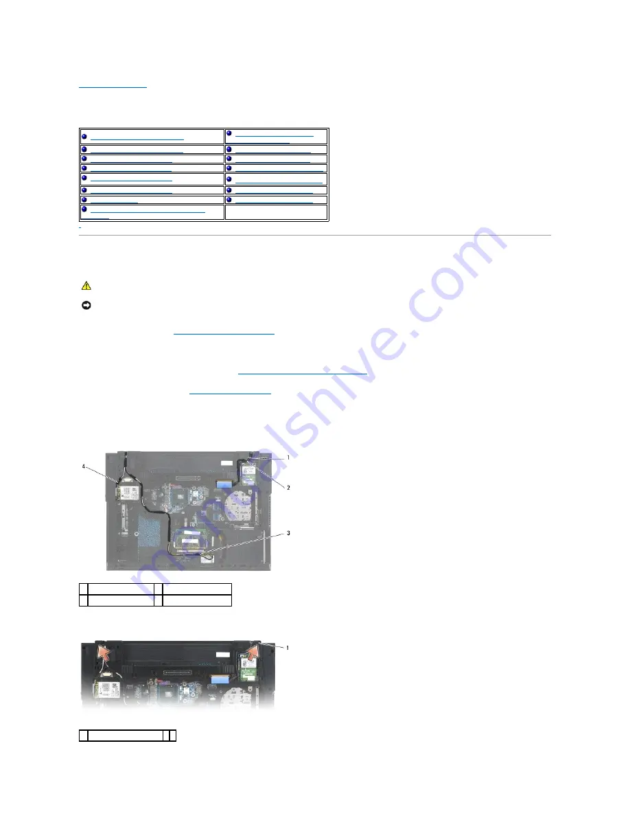
Disconnect the display cable and the wireless antenna cables.  


6.

Remove the display cable and the wireless antenna cables (WLAN, WWAN, and WPAN) from their routing channels. Position all cables to the rear and 
away from the laptop.  


7.

Remove the two M2.5 x 5-mm screws from the hinges.  


Removing the Display Assembly


Replacing the Camera and 

Microphone Assembly


Replacing the Display Assembly 


Removing the Latch Hook


Removing the Display Bezel


Replacing the Latch Hook


Replacing the Display Bezel


Removing the Display Bracket 


Removing the Display Panel


Replacing the Display Bracket


Replacing the Display Panel 


Remove the Display Cover


Display Inverter


Replace the Display Cover 


Removing the Camera and Microphone 

Assembly


CAUTION: 

Before working inside your computer, read the safety information that shipped with your computer. For additional safety best 

practices information, see the Regulatory Compliance Homepage on www.dell.com at: www.dell.com/regulatory_compliance.


NOTICE: 

Position all display assembly cables toward the back, away from the base assembly before installing the display assembly. 

1  display cable 

2  WPAN antenna cable 

3  WLAN antenna cable  4  WWAN antenna cable 

1  M2.5 x 5-mm screws (2) 


Summary of Contents for M4400 - Precision Mobile Workstation

Page 1: ... names may be used in this document to refer to either the entities claiming the marks and names or their products Dell Inc disclaims any proprietary interest in trademarks and trade names other than its own August 2008 Rev A00 Troubleshooting LED Cover Before Working on Your Computer Keyboard Base Assembly Right Speaker Grill and Fingerprint Reader Hinge Covers Flash Cache Module Hard Drive Palm ...

Page 2: ...the Bottom of the Base Assembly 1 Slide the bottom of the base assembly into place 2 Replace the M2 5 x 5 mm captive screw 3 Follow the procedure After Working on Your Computer Removing the Base Assembly 1 Follow the procedures in Before Working on Your Computer 2 Remove the battery see Removing the Battery 3 Remove the hard drive see Removing the Hard Drive 4 Remove the modular drive see Removing...

Page 3: ...ar the processor 18 Remove the palm rest assembly see Removing the Palm Rest Assembly 19 Remove the SD card reader assembly see Removing the SD Card Reader 20 Remove the Express card cage assembly see Removing the Express Card Cage 21 Disconnect the orange I O board cable from the system board 22 Remove the two M2 x 3 mm screws securing the PC card cage 23 Uncouple the PC card cage from its mounti...

Page 4: ...yboard 10 Replace the display assembly see Replacing the Display Assembly 11 Reconnect the DC power cable to the system board 12 Replace the coin cell battery see Replacing the Coin Cell Battery 13 Replace the discrete graphics heat sink see Replacing the Discrete Graphics Heat Sink 14 Replace the processor heat sink see Replacing the Processor Heat Sink 15 Replace the fan see Replacing the Fan 16...

Page 5: ...ar differently than shown in this document CAUTION Before working inside your computer read the safety information that shipped with your computer For additional safety best practices information see the Regulatory Compliance Homepage on www dell com at www dell com regulatory_compliance NOTICE Only a certified service technician should perform repairs on your computer Damage due to servicing that...

Page 6: ...cards cables and so on before turning on your computer 1 Replace the battery Slide the battery into the battery bay until it clicks into place 2 Connect any external devices such as a port replicator battery slice or cool slice and replace any cards such as an ExpressCard 3 Connect any telephone or network cables to your computer 4 Connect your computer and all attached devices to their electrical...

Page 7: ...ive 1 Ensure that the DC adapter is plugged in the main battery is properly installed and a network cable is attached 2 Turn on the computer 3 Locate the latest BIOS update file for your computer at support dell com 4 Click Download Now to download the file 5 If the Export Compliance Disclaimer window appears click Yes I Accept this Agreement The File Download window appears 6 Click Save this prog...

Page 8: ...Rest Assembly 8 If a card is in the cage remove the card 9 Remove the three M2 x 3 mm screws that secure the Express card cage to the base assembly 10 Disconnect the Express card cable from the system board 11 Lift the Express card cage away from the system board Replacing the Express Card Cage 1 Attach one side of the carrier and then the other and set it in place 2 Replace the three M2 x 3 mm sc...

Page 9: ... the Keyboard 6 Replace the display assembly see Replacing the Display Assembly 7 Replace the bottom of the base assembly see Replacing the Bottom of the Base Assembly 8 Replace the modular drive see Replacing the Modular Drive 9 Replace the hard drive see Replacing the Hard Drive 10 Follow the procedure After Working on Your Computer Back to Contents Page ...

Page 10: ...are re installing the old coin cell battery press down to secure the tape to the base assembly 4 Replace the bottom of the base assembly see Replacing the Bottom of the Base Assembly 5 Follow the procedure After Working on Your Computer Back to Contents Page CAUTION Before you begin any of the procedures in this section follow the safety instructions that shipped with your computer NOTICE Disconne...

Page 11: ......

Page 12: ...dule from the ZIF socket CAUTION Before working inside your computer read the safety information that shipped with your computer For additional safety best practices information see the Regulatory Compliance Homepage on www dell com at www dell com regulatory_compliance 1 processor module CPU NOTICE To avoid damage to the processor hold the screwdriver so that it is perpendicular to the processor ...

Page 13: ... safety best practices information see the Regulatory Compliance Homepage on www dell com at www dell com regulatory_compliance NOTICE Do not touch the processor die Press and hold the processor down on the substrate on which the die is mounted while turning the cam screw to prevent intermittent contact between the cam screw and processor NOTICE Ensure that the cam lock is in the fully open positi...

Page 14: ...equential order the four captive screws that secure the processor heat sink to the system board 6 Carefully lift the screw end of the assembly up at an angle then ease the vent end of the assembly out of the computer Removing the Discrete Graphics Heat Sink Before removing the discrete graphics heat sink the processor heat sink must be removed 1 Loosen the three captive screws that secure the grap...

Page 15: ...cessor Heat Sink 1 Place the vent end of the processor heat sink into the computer at an angle then align the four captive screws on the heat sink with the screw holes on the system board 2 In sequential order tighten the four captive screws to secure the heat sink to the system board 3 Replace the fan see Replacing the Fan 4 Replace the bottom of the base assembly see Removing the Bottom of the B...

Page 16: ... board onto the locator pins 2 Replace the two M2 x 3 mm screws to secure the I O board to the base assembly 3 Slide the wireless switch on and off to ensure that it functions without any obstruction 4 Replace the system board see Replacing the System Board Assembly 5 Follow the procedure After Working on Your Computer CAUTION Before you begin the following procedure follow the safety instructions...

Page 17: ...Back to Contents Page ...

Page 18: ...he Camera and Microphone Assembly Replacing the Display Assembly Removing the Latch Hook Removing the Display Bezel Replacing the Latch Hook Replacing the Display Bezel Removing the Display Bracket Removing the Display Panel Replacing the Display Bracket Replacing the Display Panel Remove the Display Cover Display Inverter Replace the Display Cover Removing the Camera and Microphone Assembly CAUTI...

Page 19: ...s next to the card slot 8 Connect the display cable to the display cable connector on the system board 9 Replace the hinge covers see Replacing the Hinge Covers 10 Replace the bottom of the base assembly see Replacing the Bottom of the Base Assembly 11 Replace the battery see Replacing the Battery Removing the Display Bezel 1 Follow the instructions in Before Working on Your Computer 2 Remove the ...

Page 20: ...ove the four M2 5 x 5 mm screws from the display panel NOTICE To release the snaps on the left and right sides of the bezel push the bezel sides away or out from the LCD while lifting up To release the snaps along the top and bottom of the bezel pull the bezel top or bottom toward or in to the LCD while lifting up 1 left side of display bezel 2 top of display bezel 3 latch hook on display panel 4 ...

Page 21: ... LED Display Panel 1 Follow the instructions in Before Working on Your Computer 2 Remove the display assembly see Removing the Display Assembly 3 Remove the display bezel see Removing the Display Bezel 4 Remove the four M2 5 x 5 mm screws that anchor the display panel 1 M2 5 x 5 mm screw 4 2 display panel 3 display cover 4 inverter backlight cable 1 back of display panel 2 display panel cable conn...

Page 22: ... panel using four M2 x 3 mm screws for each bracket 2 Place the display panel upside down on your workspace in front of the display cover Connect the backlight cable to the inverter Connect the display cable to the connector on the back of the display panel 3 Position the display panel in the display cover Use the alignment posts in the display cover to align each bracket 4 Connect the display cab...

Page 23: ...embly see Replacing the Display Assembly Display Inverter Removing the Display Inverter 1 Follow the instructions in Before Working on Your Computer 2 Remove the display assembly see Removing the Display Assembly 3 Remove the display bezel see Removing the Display Bezel 4 Remove the M2 x 3 mm screw from the display inverter 5 Disconnect the two display inverter connectors 6 Lift the display invert...

Page 24: ...y 2 Close the lever on the connector on the camera microphone assembly 3 Angle in and align the camera microphone assembly with the notch on the display cover 1 M2 x 3 mm screw 2 2 display inverter connector 3 display inverter 4 display inverter connector CAUTION Before working inside your computer read the safety information that shipped with your computer For additional safety best practices inf...

Page 25: ...sition the latch hook on the display cover 3 Replace the M2 5 x 5 mm screw 4 Replace the display bezel see Replacing the Display Bezel 5 Replace the display assembly see Replacing the Display Assembly Removing the Display Bracket 1 Remove the two M2 x 3mm screws from the display bracket CAUTION Before working inside your computer read the safety information that shipped with your computer For addi...

Page 26: ...ra and Microphone Assembly 3 Replace the display panel see Replacing the Display Assembly 4 Replace the display bezel see Replacing the Display Bezel 5 Replace the display assembly see Replacing the Display Assembly 6 Replace the hinge covers see Replacing the Hinge Covers 1 display panel 2 M2 x 3 mm screw 2 3 display panel bracket CAUTION Before working inside your computer read the safety inform...

Page 27: ...7 Replace the bottom of the base assembly see Replacing the Bottom of the Base Assembly 8 Follow the procedure After Working on Your Computer Back to Contents Page ...

Page 28: ...assembly 2 Install the three M2 5 x 5 mm screws to secure the fan 3 Connect the fan connector to the system board connector 4 Replace the bottom of the base assembly see Replacing the Bottom of the Base Assembly 5 Follow the procedure After Working on Your Computer Back to Contents Page CAUTION Before working inside your computer read the safety information that shipped with your computer For addi...

Page 29: ......

Page 30: ...ving the Bottom of the Base Assembly 3 If removing a module from the WPAN Mini Card slot remove the left hinge cover see Removing the Hinge Covers 4 Remove the M2 x 3 mm screw from the FCM The module pops up to a 30 degree angle to the system board 5 Slide the FCM out of its connector CAUTION Before working inside your computer read the safety information that shipped with your computer For additi...

Page 31: ...he base assembly see Removing the Bottom of the Base Assembly 6 Follow the procedure After Working on Your Computer Back to Contents Page NOTICE The connectors are keyed to ensure correct insertion If you feel resistance check the connectors on the module and on the system board and realign the module NOTICE To avoid damage to the FCM ensure the cables are not under the module when you install it ...

Page 32: ...AUTION Before working inside your computer read the safety information that shipped with your computer For additional safety best practices information see the Regulatory Compliance Homepage on www dell com at www dell com regulatory_compliance CAUTION Do not touch the metal housing of the hard drive if you remove the hard drive from the computer while the drive is hot NOTICE To prevent data loss ...

Page 33: ...ter 6 Start up your computer 7 If you have installed a new or different hard drive try to restart your computer If it doesn t restart l use your Operating System installation media to install the operating system for your computer see your Setup and Quick Reference Guide for information l use the Drivers and Utilities media to install the drivers and utilities for your computer see your Setup and ...

Page 34: ...emove the two M2 5 x 5 mm screws from each hinge cover 5 Slide each hinge cover off the computer and lift to remove it Replacing the Hinge Covers 1 Slide the left hinge cover over the display port and slide the right hinge cover over the RJ 45 network connector 2 Replace the M2 5x5 mm screws in each hinge cover 3 Replace the bottom of the base assembly see Replacing the Bottom of the Base Assembly...

Page 35: ... beneath the front inside edge of the palm rest 2 Carefully press each side to snap the keyboard into place 3 Replace the two M2 x 3 mm screws at the top of the keyboard CAUTION Before you begin any of the procedures in this section follow the safety instructions that shipped with your computer NOTICE The key caps on the keyboard are fragile easily dislodged and time consuming to replace Exercise ...

Page 36: ...he LED cover see Replacing the LED Cover 5 Close the display and turn the computer over 6 Follow the procedure After Working on Your Computer Back to Contents Page 1 keyboard connector 2 tabs 5 3 M2 x 3 mm screw 2 ...

Page 37: ... remainder of the cover to remove it from the laptop Replacing the LED Cover 1 Snap the LED cover back into place one tab at a time 2 Follow the procedure After Working on Your Computer Back to Contents Page CAUTION Before you begin any of the procedures in this section follow the safety instructions that shipped with your computer 1 LED cover 2 scribe CAUTION Before you begin any of the procedure...

Page 38: ...module and lift the free edge of the module so that it sits at about a 30 degree angle to the system board CAUTION Before you begin any of the procedures in this section follow the safety instructions in the Dell Product Information Guide CAUTION To avoid electrostatic discharge ground yourself by using a wrist grounding strap or by periodically touching an unpainted metal surface such as a connec...

Page 39: ...et it must be removed before a memory module in the DIMM A socket can be replaced 1 Ground yourself by touching a bare metal part in the computer chassis 2 Remove the memory module from its anti static packaging and grasping the module at the side edges align the slot in the module edge connector with the key in the DIMM A socket connector 3 Slide the memory module into the socket connector at a 3...

Page 40: ...d tighten the captive screw 2 Follow the procedure After Working on Your Computer 3 Set the computer upright and open the display 4 Power on your computer As the computer boots it detects the additional memory and automatically updates the system configuration information Verify that the memory capacity shown on the display is what is expected 5 To confirm the amount of memory installed in the com...

Page 41: ...to the modem 2 Place the modem into the base assembly 3 Replace the M2 x 3 mm screw to secure the modem to the I O board 4 Connect the orange modem flex cable to the I O board 5 Replace the bottom of the base assembly see Replacing the Bottom of the Base Assembly CAUTION Before working inside your computer read the safety information that shipped with your computer For additional safety best pract...

Page 42: ...6 Follow the procedure After Working on Your Computer Back to Contents Page ...

Page 43: ... into the modular bay until it is properly seated 2 Push the release latch in to secure the drive 3 If a security screw was removed replace the security screw 4 Follow the procedure After Working on Your Computer Back to Contents Page CAUTION Before you begin any of the procedures in this section follow the safety instructions that shipped with your computer NOTE The modular drive security screw i...

Page 44: ...ter over and remove ten M2 5 x 5 mm screws and one M2 5 x 8 mm screw 10 Loosen the three captive screws on the underside of the laptop with the front edge toward you l One screw near the front of the right side edge of the laptop l One in the middle of the left side edge of the laptop l One near the upper left corner marked with an S 11 Turn the computer topside up and remove the four M2 5 x 5 mm ...

Page 45: ...ng the Palm Rest Assembly 1 Attach the left and right speakers to the palm rest using two screws for each Route the speaker cable through the palm rest assembly 2 Position the palm rest assembly over the computer and attach the cable from the palm rest assembly to the I O board 1 thermal plate 2 M2 5 x 4 mm screw 4 NOTICE Do not use force to separate the palm rest from the computer If you encounte...

Page 46: ...e fingerprint reader cable optional to the system board 9 Turn the computer over and replace the ten M2 5 x 5 5 mm screws and the one M2 5 x 8 mm screw on the bottom of the computer to secure the palm rest 10 Replace the discrete graphics heat sink see Replacing the Discrete Graphics Heat Sink 11 Replace the processor heat sink see Replacing the Processor Heat Sink 12 Replace the fan see Replacing...

Page 47: ...r Heat Sink 12 Remove the discrete graphics heat sink see Removing the Discrete Graphics Heat Sink 13 Remove the fingerprint reader speaker cover see Removing the Right Speaker Grill and Fingerprint Reader 14 Remove the palm rest assembly see Removing the Palm Rest Assembly 15 Remove the card cage see Removing the Express Card Cage 16 Remove three M2 5 x 5 mm screws labeled with white arrows from ...

Page 48: ...essor Heat Sink 9 Replace the fan see Replacing the Fan 10 Replace the keyboard see Replacing the Keyboard 11 Replace the LED cover see Replacing the LED Cover 12 Replace the display assembly see Replacing the Display Assembly 13 Replace the hinge covers see Replacing the Hinge Covers 14 Replace the bottom of the base assembly see Replacing the Bottom of the Base Assembly 15 Replace the modular dr...

Page 49: ... Removing the Palm Rest Assembly 8 If a card is in the SD card reader remove the card 9 Disconnect the SD card reader cable from the system board 10 Remove the two M2 5 x 3 mm screws that secure the SD card reader 11 Remove the SD card reader assembly from the base assembly Replacing the SD Card Reader 1 Position the SD card reader in the base assembly 2 Replace the two M2 5 x 3 mm screws to secur...

Page 50: ... the Keyboard 6 Replace the display assembly see Replacing the Display Assembly 7 Replace the modular drive see Replacing the Modular Drive 8 Replace the hard drive see Replacing the Hard Drive 9 Replace the bottom of the base assembly see Replacing the Bottom of the Base Assembly 10 Follow the procedure After Working on Your Computer Back to Contents Page ...

Page 51: ... the LED Cover 5 Remove the keyboard see Removing the Keyboard 6 Remove the bottom of the base assembly see Removing the Bottom of the Base Assembly 7 Loosen the two captured screws indicated by an S stenciled on the base plate 8 Remove the fingerprint reader cable 9 Remove the plastic speaker fingerprint reader grill CAUTION Before working inside your computer read the safety information that shi...

Page 52: ...over 7 Replace the modular drive see Replacing the Modular Drive 8 Replace the hard drive see Replacing the Hard Drive 9 Follow the procedure After Working on Your Computer Back to Contents Page 1 fingerprint reader cable connector 2 fingerprint reader cable 3 speaker fingerprint reader grill 1 screw 3 2 left speaker 3 underside of palm rest 4 speaker cables 5 right speaker CAUTION Before working ...

Page 53: ...WPAN UWB FCM slot if present see Removing a WPAN UWB Card 11 Remove the memory modules see Removing a Memory Module 12 Remove the fan see Removing the Fan 13 Remove the processor heat sink see Removing the Processor Heat Sink 14 Remove the processor see Removing the Processor Module 15 Remove the discrete graphics heat sink see Removing the Discrete Graphics Heat Sink 16 Disconnect the coin cell b...

Page 54: ...onnector 3 Position the system board into the base ensure that the DC USB and serial connectors fit into the base assembly 4 Replace the five M2 5 x 4 mm screws to secure the system board 5 Connect the I O board cable to the system board 6 Replace the PC card cage by gently pushing the inward end of the cage down over its mounting bracket 1 M2 x 3 mm screw 2 2 PC card cage 3 latch tab 4 plastic sc...

Page 55: ...les see Replacing a Memory Module 25 Replace the WPAN UWB FCM card if one was installed see Replacing a WPAN UWB Card 26 Replace the WLAN WiMax card if one was installed see Replacing a WLAN Card 27 Replace the WWAN FCM card if one was installed see Replacing a WWAN Card 28 Replace the bottom of the base assembly see Replacing the Bottom of the Base Assembly 29 Replace the modular drive see Removi...

Page 56: ...Windows Start button logo are either trademarks or registered trademarks of Microsoft Corporation in the United States and or other countries Other trademarks and trade names may be used in this document to refer to either the entities claiming the marks and names or their products Dell Inc disclaims any proprietary interest in trademarks and trade names other than its own June 2008 Rev A00 Back t...

Page 57: ...ory modules are detected l If two or more memory modules are installed remove the modules see Removing a Memory Module then reinstall one module see Replacing a Memory Module and restart the computer If the computer starts normally continue to install additional memory modules one at a time until you have identified a faulty module or reinstalled all modules without error l If available install wo...

Page 58: ...d keyboard display memory hard drive etc l During the assessment answer any questions that appear l If failures are detected during the Pre boot System Assessment write down the error code s and contact Dell Support l If the Pre boot System Assessment completes successfully the following message appears Booting Dell Diagnostic Utility Partition Press any key to continue 3 Press any key to start th...

Page 59: ...ostics Main Menu left click with the mouse or press Tab and then Enter to select the test you want to run see Dell Diagnostics Main Menu 10 After all tests have completed close the test window to return to the Dell Diagnostics Main Menu 11 Close the Main Menu window to exit the Dell Diagnostics and restart the computer 12 Remove the Drivers and Utilities media from the optical drive Dell Diagnosti...

Page 60: ...f devices in the system This typically can take 10 to 20 minutes NOTE The Express Test requires no interaction on your part Run Express Test first to increase the possibility of tracing a problem quickly Extended Test Performs a thorough check of devices in the system This typically can take 1 hour or more NOTE The Extended Test periodically requires your input to answer specific questions Custom ...

Page 61: ...appears on the screen write down the exact message This message may help support personnel diagnose and fix the problem s l If an error message occurs in a program see the program s documentation Battery Problems Drive Problems Ensure that Microsoft Windows Recognizes the drive Windows XP l Click Start and click My Computer Windows Vista l Click Start and click Computer If the drive is not listed ...

Page 62: ...ng all programs before you write to the optical Turn off standby mode in Windows before writing to a disc For information about setting power options see the Dell Technology Guide on your computer or at support dell com You can also search for the keyword standby in Windows Help and Support for information on power management modes Hard drive problems Run Check Disk Windows XP 1 Click Start and cl...

Page 63: ...t If you have problems with an IEEE 1394 device not provided by Dell Contact the IEEE 1394 device manufacturer Lockups and Software Problems The computer does not start up Check the diagnostic lights See Power Problems Ensure that the power cable is firmly connected to the computer and to the electrical outlet The computer stops responding Turn the computer off If you are unable to get a response ...

Page 64: ... to get a response by pressing a key on your keyboard or moving your mouse press and hold the power button for at least 8 to 10 seconds until the computer turns off and then restart your computer Other software problems Check the software documentation or contact the software manufacturer for troubleshooting information l Ensure that the program is compatible with the operating system installed on...

Page 65: ...rking by testing it with another device such as a lamp Eliminate interference Some possible causes of interference are l Power keyboard and mouse extension cables l Too many devices connected to the same power strip l Multiple power strips connected to the same electrical outlet Sound and Speaker Problems No sound from speakers Adjust the Windows volume control Click or double click the speaker ic...

Page 66: ...itor brightness and contrast controls If the external monitor works the computer display or video controller may be defective Contact Dell Support Dell Technical Update Service The Dell Technical Update service provides proactive e mail notification of software and hardware updates for your computer The service is free and can be customized for content format and how frequently you receive notific...

Page 67: ...e computer over 3 Remove the bottom of the base assembly see Removing the Bottom of the Base Assembly 4 Disconnect the antenna cables from the WLAN card 5 Remove the M2 x 3 mm screw securing the WLAN card The card will pop up to a 30 degree angle to the system board 6 Slide the WLAN card out of its connector at a 30 degree angle to the system board Replacing a WLAN Card CAUTION Before you begin an...

Page 68: ... on the label white black and gray connect the white antenna cable to the white triangle connect the black antenna cable to the black triangle and connect the gray antenna cable to the gray triangle 5 Replace the bottom of the base assembly see Removing the Bottom of the Base Assembly 6 Follow the procedure After Working on Your Computer Back to Contents Page NOTICE The connectors are keyed to ens...

Page 69: ...y and turn the computer over 3 Remove the bottom of the base assembly see Removing the Bottom of the Base Assembly 4 Remove the left hinge cover see Removing the Hinge Covers 5 Disconnect the blue antenna cable from the WPAN UWB card 6 Remove the M2 x 3 mm screw from the WPAN UWB card The card will pop up to a 30 degree angle to the system board 7 Slide the WPAN UWB card out of its connector CAUTI...

Page 70: ...e WPAN UWB card 5 Install the left hinge cover see Replacing the Hinge Covers 6 Install the bottom of the base assembly see Removing the Bottom of the Base Assembly 7 Follow the procedure After Working on Your Computer Back to Contents Page NOTICE To avoid damage to the WPAN UWB card ensure the cables are not under the card when you replace the card NOTICE The Mini Card slot has a WPAN UWB FCM lab...

Page 71: ...the display and turn the computer over 3 Remove the bottom of the base assembly see Removing the Bottom of the Base Assembly 4 Disconnect the antenna cables from the WWAN card 5 Remove the M2 x 3 mm screw that secures the WWAN card The card will pop up to a 30 degree angle to the system board 6 Slide the WWAN card out of its connector Replacing a WWAN Card CAUTION Before you begin any of the proce...

Page 72: ...5 Replace the bottom of the base assembly see Removing the Bottom of the Base Assembly 6 Follow the procedure After Working on Your Computer Back to Contents Page NOTICE The connectors are keyed to ensure correct insertion If you feel resistance check the connectors on the card and on the system board and realign the card NOTICE To avoid damage to the WWAN card ensure the cables are not under the ...

Reviews: