background image

Back to Contents Page


 Processor  

Dell™ Inspiron™ One 2205 Service Manual 


Removing the Processor 


Replacing the Processor 


Removing the Processor  


1.

Follow the instructions in 

Before You Begin

.  


2.

Remove the back cover (see 

Removing the Back Cover

).  


3.

Follow the instructions from 

step 3

 to 

step 7

 in 

Removing the Front Stand

.  


4.

Remove the rear stand cover (see 

Removing the Rear Stand Cover

).  


5.

Remove the system-board shield (see 

Removing the System-Board Shield

).  


6.

Remove the MXM-assembly fan (see 

Removing the MXM-Assembly Fan

).  


7.

Remove the MXM assembly (see 

Removing the MXM Assembly

).  


8.

Remove the processor heat-sink fan (see 

Removing the Processor Heat-Sink Fan

).  


9.

Remove the processor heat-sink (see 

Removing the Processor Heat-Sink

).  


10.

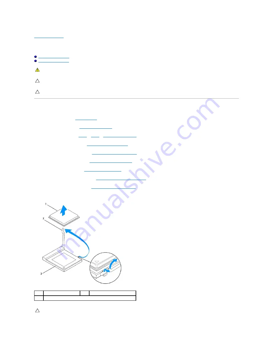
Press and push the release lever down and out to release it from the tab that secures it.  


WARNING: 

Before working inside your computer, read the safety information that shipped with your computer. For additional safety best 

practices information, see the Regulatory Compliance Homepage at www.dell.com/regulatory_compliance. 


CAUTION: 

Only a certified service technician should perform repairs on your computer. Damage due to servicing that is not authorized by Dell™ 

is not covered by your warranty.


CAUTION: 

To avoid electrostatic discharge, ground yourself by using a wrist grounding strap or by periodically touching an unpainted metal 

surface (such as a connector on your computer).

processor 

release lever 

processor socket 


CAUTION: 

When removing or replacing the processor, do not touch any of the pins inside the processor socket or allow any objects to fall on the 

pins in the processor socket.

Summary of Contents for Inspiron One 2205

Page 1: ...emarks and trade names other than its own Regulatory model W03B series Regulatory type W03B001 August 2010 Rev A00 Technical Overview Before You Begin Back Cover Hard Drive Optical Drive Memory Module s Converter Card Touch Screen Control Card Optional Front Stand Rear Stand Cover Rear Stand System Board Shield Antenna In Connector Optional Infrared Blaster Connector Optional B CAS Card Optional C...

Page 2: ...re working inside your computer read the safety information that shipped with your computer For additional safety best practices information see the Regulatory Compliance Homepage at www dell com regulatory_compliance CAUTION Only a certified service technician should perform repairs on your computer Damage due to servicing that is not authorized by Dell is not covered by your warranty CAUTION To ...

Page 3: ...d devices to electrical outlets and turn them on Back to Contents Page CAUTION Before turning on the computer replace all screws and ensure that no stray screws remain inside the computer Failure to do so may result in damage to the computer ...

Page 4: ... the computer Replacing the B CAS Card 1 Follow the instructions in Before You Begin 2 Carefully slide the B CAS card into the B CAS card location 3 Align the screw holes on the B CAS card with the screw holes on the chassis 4 Connect the B CAS card cable to the connector on the TV tuner card WARNING Before working inside your computer read the safety information that shipped with your computer Fo...

Page 5: ...ollow the instructions from step 4 to step 7 in Replacing the Front Stand 9 Replace the back cover see Replacing the Back Cover 10 Connect your computer and all attached devices to electrical outlets and turn them on Back to Contents Page CAUTION Before turning on the computer replace all screws and ensure that no stray screws remain inside the computer Failure to do so may result in damage to the...

Page 6: ...uter and all attached devices CAUTION To avoid losing data save and close all open files and exit all open programs before you turn off your computer WARNING Before working inside your computer read the safety information that shipped with your computer For additional safety best practices information see the Regulatory Compliance Homepage at www dell com regulatory_compliance WARNING Disconnect a...

Page 7: ... to ground the system board Back to Contents Page CAUTION To disconnect a network cable first unplug the cable from your computer and then unplug the cable from the network device CAUTION Before touching anything inside your computer ground yourself by touching an unpainted metal surface such as the metal at the back of the computer While you work periodically touch an unpainted metal surface to d...

Page 8: ...duct brand in the Select Your Product Line list d Select the product model number in the Select Your Product Model list e Click Confirm 4 A list of results appear on the screen Click BIOS 5 Click Download Now to download the latest BIOS file The File Download window appears 6 Click Save to save the file on your desktop The file downloads to your desktop 7 Click Close if the Download Complete windo...

Page 9: ...tions in Before You Begin 2 Connect the Bluetooth card cable to the connector on the Bluetooth card 3 Align the screw holes on the Bluetooth card with the screw holes on the display bezel 4 Replace the two screws that secure the Bluetooth card to the display bezel 5 Replace the mylar sleeve on the Bluetooth card WARNING Before working inside your computer read the safety information that shipped w...

Page 10: ...e Display Bezel 8 Connect your computer and all attached devices to electrical outlets and turn them on Back to Contents Page CAUTION Before turning on the computer replace all screws and ensure that no stray screws remain inside the computer Failure to do so may result in damage to the computer ...

Page 11: ...amera module with the screw holes on the display bezel 4 Replace the two screws that secure the camera module to the display bezel 5 Turn the display bezel over 6 Follow the instructions from step 5 to step 12 in Replacing the Display Bezel WARNING Before working inside your computer read the safety information that shipped with your computer For additional safety best practices information see th...

Page 12: ...d devices to electrical outlets and turn them on Back to Contents Page CAUTION Before turning on the computer replace all screws and ensure that no stray screws remain inside the computer Failure to do so may result in damage to the computer ...

Page 13: ... your computer read the safety information that shipped with your computer For additional safety best practices information see the Regulatory Compliance Homepage at www dell com regulatory_compliance CAUTION Only a certified service technician should perform repairs on your computer Damage due to servicing that is not authorized by Dell is not covered by your warranty CAUTION To avoid electrostat...

Page 14: ...tand Cover 8 Follow the instructions from step 4 to step 7 in Replacing the Front Stand 9 Replace the back cover see Replacing the Back Cover 10 Connect your computer and all attached devices to electrical outlets and turn them on Back to Contents Page 1 Mini Card 2 system board connector 3 screws 2 CAUTION The connectors are keyed to ensure correct insertion Use of excessive force may damage the ...

Page 15: ...computer read the safety information that shipped with your computer For additional safety best practices information see the Regulatory Compliance Homepage at www dell com regulatory_compliance WARNING A new battery can explode if it is incorrectly installed Replace the battery only with the same or equivalent type recommended by the manufacturer Discard used batteries according to the manufactur...

Page 16: ...e the back cover see Replacing the Back Cover 7 Connect your computer and devices to electrical outlets and then turn them on 8 Enter the system setup utility see System Setup Utility and restore the settings you recorded in step 1 Back to Contents Page CAUTION Before turning on the computer replace all screws and ensure that no stray screws remain inside the computer Failure to do so may result i...

Page 17: ...ngertips carefully pry up the inside edge of the display bezel 9 Lift the display bezel away from the computer 10 Remove the camera module see Removing the Camera Module 11 Remove the infrared card see Removing the Infrared Card 12 Remove the Bluetooth card see Removing the Bluetooth Card WARNING Before working inside your computer read the safety information that shipped with your computer For ad...

Page 18: ... that adheres the camera module to the chassis 11 Replace the 19 screws that secure the display bezel to the chassis 12 Replace the system board see Replacing the System Board 13 Connect your computer and all attached devices to electrical outlets and turn them on Display Panel Removing the Display Panel 1 Follow the instructions in Before You Begin 2 Follow the instructions from step 2 to step 9 ...

Page 19: ...ttached devices to electrical outlets and turn them on Display Cable Removing the Display Cable 1 Follow the instructions in Before You Begin 2 Remove the display panel see Removing the Display Panel 3 Turn the display panel over 4 Pull the pull tab to disconnect the display cable from the connector on the display panel 1 screws 4 2 display panel NOTE The number of screws that secure the display p...

Page 20: ...el see Replacing the Display Panel 5 Connect your computer and all attached devices to electrical outlets and turn them on Back to Contents Page 1 display cable 2 display cable connector 3 pull tab 4 back of the display panel CAUTION Before turning on the computer replace all screws and ensure that no stray screws remain inside the computer Failure to do so may result in damage to the computer ...

Page 21: ...t the cables to the connectors on the touch screen control card 5 Replace the back cover see Replacing the Back Cover 6 Connect your computer and all attached devices to electrical outlets and turn them on WARNING Before working inside your computer read the safety information that shipped with your computer For additional safety best practices information see the Regulatory Compliance Homepage at...

Page 22: ...Back to Contents Page ...

Page 23: ...e three screws that secure the I O bracket to the front stand 9 Release the four tabs that secure the I O bracket to the front stand 10 Remove the I O bracket from the front stand WARNING Before working inside your computer read the safety information that shipped with your computer For additional safety best practices information see the Regulatory Compliance Homepage at www dell com regulatory_c...

Page 24: ...iddle frame 6 Align the screw holes on the front stand assembly with the screw holes on the computer 7 Replace the three screws that secure the front stand assembly to the computer 8 Replace the back cover see Replacing the Back Cover 9 Connect your computer and all attached devices to electrical outlets and turn them on Back to Contents Page 1 front stand 2 I O bracket 3 screws 3 4 tabs 4 CAUTION...

Page 25: ... the hard drive from the computer when the drive is hot do not touch the metal housing of the hard drive CAUTION Only a certified service technician should perform repairs on your computer Damage due to servicing that is not authorized by Dell is not covered by your warranty CAUTION To avoid electrostatic discharge ground yourself by using a wrist grounding strap or by periodically touching an unp...

Page 26: ... 5 Place the hard drive assembly on the chassis and slide the hard drive assembly into place 6 Tighten the two captive screws that secure the hard drive assembly to the chassis 7 Replace the back cover see Replacing the Back Cover 8 Connect your computer and all attached devices to electrical outlets and turn them on Back to Contents Page 1 screws 4 2 hard drive cage 3 hard drive CAUTION Before tu...

Page 27: ...ink to the system board 11 Carefully lift the processor heat sink away from the computer Replacing the Processor Heat Sink WARNING Before working inside your computer read the safety information that shipped with your computer For additional safety best practices information see the Regulatory Compliance Homepage at www dell com regulatory_compliance WARNING The heat sink may be very hot during no...

Page 28: ... 9 Replace the rear stand cover see Replacing the Rear Stand Cover 10 Follow the instructions from step 4 to step 7 in Replacing the Front Stand 11 Replace the back cover see Replacing the Back Cover 12 Connect your computer and all attached devices to electrical outlets and turn them on Back to Contents Page CAUTION Incorrect alignment of the processor heath sink can cause damage to the system bo...

Page 29: ...g the Processor Heat Sink Fan 1 Follow the instructions in Before You Begin 2 Align the screw holes on the processor heat sink fan with the screw holes on the chassis 3 Replace the two screws that secure the processor heat sink fan to the chassis WARNING Before working inside your computer read the safety information that shipped with your computer For additional safety best practices information ...

Page 30: ...ee Replacing the Rear Stand Cover 8 Follow the instructions from step 4 to step 7 in Replacing the Front Stand 9 Replace the back cover see Replacing the Back Cover 10 Connect your computer and all attached devices to electrical outlets and turn them on Back to Contents Page CAUTION Before turning on the computer replace all screws and ensure that no stray screws remain inside the computer Failure...

Page 31: ...ssis 5 Replace the back cover see Replacing the Back Cover 6 Connect your computer and all attached devices to electrical outlets and turn them on WARNING Before working inside your computer read the safety information that shipped with your computer For additional safety best practices information see the Regulatory Compliance Homepage at www dell com regulatory_compliance CAUTION Only a certifie...

Page 32: ...Back to Contents Page ...

Page 33: ...tor to the system board shield 4 Follow the instructions from step 4 to step 11 in Replacing the System Board Shield 5 Connect your computer and all attached devices to electrical outlets and turn them on Back to Contents Page WARNING Before working inside your computer read the safety information that shipped with your computer For additional safety best practices information see the Regulatory C...

Page 34: ......

Page 35: ...n the infrared card 3 Align the screw holes on the infrared card with the screw holes on the display bezel 4 Replace the screw that secures the infrared card to the display bezel 5 Turn the display bezel over WARNING Before working inside your computer read the safety information that shipped with your computer For additional safety best practices information see the Regulatory Compliance Homepage...

Page 36: ... 7 Connect your computer and all attached devices to electrical outlets and turn them on Back to Contents Page CAUTION Before turning on the computer replace all screws and ensure that no stray screws remain inside the computer Failure to do so may result in damage to the computer ...

Page 37: ...ficult to remove gently ease the memory module back and forth to remove it from the memory module connector 8 Remove the memory module from the memory module connector Replacing Memory Module s WARNING Before working inside your computer read the safety information that shipped with your computer For additional safety best practices information see the Regulatory Compliance Homepage at www dell co...

Page 38: ...onnect your computer and all attached devices to electrical outlets and then turn them on 9 When the message appears stating that memory size has changed press F1 to continue 10 Log on to your computer To verify that the memory is installed correctly click Start Control Panel System and Security System Check the amount of memory RAM listed Back to Contents Page CAUTION If the memory module is not ...

Page 39: ...e cables from the routing guides on the middle frame 10 Remove the 13 screws that secure the middle frame to the chassis 11 Lift the middle frame at an angle toward the side of the computer and out of the chassis 12 Remove the speaker see Removing the Speakers Replacing the Middle Frame WARNING Before working inside your computer read the safety information that shipped with your computer For addi...

Page 40: ...o the connector CN10 on the system board 8 Replace the system board shield see Replacing the System Board Shield 9 Replace the rear stand cover see Replacing the Rear Stand Cover 10 Follow the instructions from step 4 to step 7 in Replacing the Front Stand 11 Follow the instructions from step 5 to step 7 in Replacing the Optical Drive 12 Replace the back cover see Replacing the Back Cover 13 Conne...

Page 41: ...ssembly with the tab in the MXM assembly connector 3 Insert the MXM assembly at a 45 degree angle into the MXM assembly connector 4 Replace the three screws that secure the MXM assembly to the chassis WARNING Before working inside your computer read the safety information that shipped with your computer For additional safety best practices information see the Regulatory Compliance Homepage at www ...

Page 42: ...ollow the instructions from step 4 to step 7 in Replacing the Front Stand 9 Replace the back cover see Replacing the Back Cover 10 Connect your computer and all attached devices to electrical outlets and turn them on Back to Contents Page CAUTION Before turning on the computer replace all screws and ensure that no stray screws remain inside the computer Failure to do so may result in damage to the...

Page 43: ...away from the system board Replacing the MXM Assembly Fan 1 Follow the instructions in Before You Begin 2 Align the screw holes on the MXM assembly fan with the screw holes on the hex nut screws 3 Adhere the silver foil on the MXM assembly heat sink 4 Replace the two screws that secure the MXM assembly fan to the hex nut screws WARNING Before working inside your computer read the safety informatio...

Page 44: ...over 8 Follow the instructions from step 4 to step 7 in Replacing the Front Stand 9 Replace the back cover see Replacing the Back Cover 10 Connect your computer and all attached devices to electrical outlets and turn them on Back to Contents Page CAUTION Before turning on the computer replace all screws and ensure that no stray screws remain inside the computer Failure to do so may result in damag...

Page 45: ...al drive 7 Remove the optical drive bracket from the optical drive 8 Pull the optical drive bezel to detach it from the optical drive WARNING Before working inside your computer read the safety information that shipped with your computer For additional safety best practices information see the Regulatory Compliance Homepage at www dell com regulatory_compliance CAUTION Only a certified service tec...

Page 46: ...lide the optical drive into the optical drive bay 6 Replace the screw that secures the optical drive to the chassis 7 Connect the power and data cables to the connectors on the optical drive 8 Replace the back cover see Replacing the Back Cover 9 Connect your computer and all attached devices to electrical outlets and turn them on Back to Contents Page 1 screws 2 2 optical drive bracket 3 optical ...

Page 47: ...or Heat Sink 10 Press and push the release lever down and out to release it from the tab that secures it WARNING Before working inside your computer read the safety information that shipped with your computer For additional safety best practices information see the Regulatory Compliance Homepage at www dell com regulatory_compliance CAUTION Only a certified service technician should perform repair...

Page 48: ...he Processor Heat Sink 11 Replace the processor heat sink fan see Replacing the Processor Heat Sink Fan 12 Replace the MXM assembly see Replacing the MXM Assembly 13 Replace the MXM assembly fan see Replacing the MXM Assembly Fan 14 Replace the system board shield see Replacing the System Board Shield CAUTION Ground yourself by touching an unpainted metal surface 1 processor socket 2 processor pin...

Page 49: ...nd 17 Replace the back cover see Replacing the Back Cover 18 Connect your computer and all attached devices to electrical outlets and then turn them on Back to Contents Page CAUTION Before turning on the computer replace all screws and ensure that no stray screws remain inside the computer Failure to do so may result in damage to the computer ...

Page 50: ...tor cable from the routing guides on the system board shield 10 Follow the instructions from step 3 to step 5 in Removing the Antenna In Connector 11 Follow the instructions from step 3 to step 5 in Removing the Infrared IR Blaster Connector Replacing the System Board Shield 1 Follow the instructions in Before You Begin 2 Follow the instructions from step 2 to step 3 in Replacing the Infrared IR B...

Page 51: ...lign the screw holes on the system board shield with the screw holes on the chassis 8 Replace the four screws that secure the system board shield to the chassis 9 Replace the rear stand cover see Replacing the Rear Stand Cover 10 Follow the instructions from step 4 to step 7 in Replacing the Front Stand 11 Replace the back cover see Replacing the Back Cover 12 Connect your computer and all attache...

Page 52: ... the middle frame 11 Lift the speakers along with its cable off the middle frame Replacing the Speakers 1 Follow the instructions in Before You Begin 2 Align the screw holes on the speakers with the screw holes on the middle frame 3 Replace the four screws two on each speaker that secure the speaker to the middle frame 4 Turn the middle frame over WARNING Before working inside your computer read t...

Page 53: ...ear Stand Cover 9 Follow the instructions from step 4 to step 7 in Replacing the Front Stand 10 Follow the instructions from step 5 to step 7 in Replacing the Optical Drive 11 Replace the back cover see Replacing the Back Cover 12 Connect your computer and all attached devices to electrical outlets and turn them on Back to Contents Page CAUTION Before turning on the computer replace all screws and...

Page 54: ...chassis 3 Align the screw holes on the speaker cover with the screw holes on the chassis 4 Replace the seven screws that secure the speaker cover to the chassis 5 Follow the instructions from step 5 to step 11 in Replacing the Display Bezel WARNING Before working inside your computer read the safety information that shipped with your computer For additional safety best practices information see th...

Page 55: ...your computer and all attached devices to electrical outlets and turn them on Back to Contents Page CAUTION Before turning on the computer replace all screws and ensure that no stray screws remain inside the computer Failure to do so may result in damage to the computer ...

Page 56: ...nd hinge into the slot on the chassis 3 Replace the three screws at the top of the rear stand hinge 4 Lift and hold the rear stand and replace the two screws at the bottom of the rear stand hinge 5 Replace the rear stand cover see Replacing the Rear Stand Cover 6 Follow the instructions from step 4 to step 7 in Replacing the Front Stand WARNING Before working inside your computer read the safety i...

Page 57: ...ur computer and all attached devices to electrical outlets and turn them on Back to Contents Page CAUTION Before turning on the computer replace all screws and ensure that no stray screws remain inside the computer Failure to do so may result in damage to the computer ...

Page 58: ...eplacing the Front Stand 5 Replace the back cover see Replacing the Back Cover 6 Connect your computer and all attached devices to electrical outlets and turn them on WARNING Before working inside your computer read the safety information that shipped with your computer For additional safety best practices information see the Regulatory Compliance Homepage at www dell com regulatory_compliance CAU...

Page 59: ...Back to Contents Page ...

Page 60: ...e Removing the Processor 13 Disconnect all the cables connected to the system board 14 Using a hex nut driver remove the two hex nut screws that secure the system board to the chassis 15 Remove the eight screws that secure the system board to the chassis 16 Lift the system board at an angle toward the side of the computer and out of the chassis WARNING Before working inside your computer read the ...

Page 61: ...mory Module s 11 Replace the MXM assembly see Replacing the MXM Assembly 12 Replace the MXM assembly fan see Replacing the MXM Assembly Fan 13 Replace the system board shield see Replacing the System Board Shield 14 Replace the rear stand cover see Replacing the Rear Stand Cover 15 Follow the instructions from step 4 to step 7 in Replacing the Front Stand 16 Replace the back cover see Replacing th...

Page 62: ...1 Turn on the computer 2 Press F2 during POST to enter the system setup program 3 Navigate to the main tab and enter the service tag in the Service Tag Setting field Back to Contents Page ...

Page 63: ...top Then shut down your computer see Turning Off Your Computer and try again Setup Item This field appears on the left side of the system setup window The field is a scrollable list containing features that define the configuration of your computer including installed hardware power conservation and security features Scroll up and down the list with the up and down arrow keys As an option is highl...

Page 64: ...te On or Off On by default l Keyboard Errors Report or Do Not Report Report by default CPU Feature l Secure Virtual Machine Disabled Mode Enabled or Disabled Enabled by default l AMD Cool N Quiet Enabled or Disabled Enabled by default Security Admin Password Allows to set change or delete the administrator password NOTE Deleting the administrator password will delete the system password Hence the ...

Page 65: ...screen press F12 The Boot Device Menu appears listing all available boot devices 4 On the Boot Device Menu choose the device you want to boot from For example if you are booting to a USB memory key highlight USB Storage Device and press Enter Changing Boot Sequence for Future Boots 1 Enter system setup utility see Entering System Setup Utility 2 Use the arrow keys to highlight the Boot menu option...

Page 66: ...2 Remove the back cover see Removing the Back Cover 3 Remove the system board shield see Removing the System Board Shield 4 Locate the 3 pin CMOS reset jumper CLR_CMOS on the system board see System Board Components CAUTION Before turning on the computer replace all screws and ensure that no stray screws remain inside the computer Failure to do so may result in damage to the computer WARNING Befor...

Page 67: ... pins 2 and 3 8 Replace the system board shield see Replacing the System Board Shield 9 Replace the back cover see Replacing the Back Cover 10 Connect your computer and devices to electrical outlets and turn them on Back to Contents Page CAUTION Before turning on the computer replace all screws and ensure that no stray screws remain inside the computer Failure to do so may result in damage to the ...

Page 68: ...m regulatory_compliance CAUTION Only a certified service technician should perform repairs on your computer Damage due to servicing that is not authorized by Dell is not covered by your warranty CAUTION To avoid electrostatic discharge ground yourself by using a wrist grounding strap or by periodically touching an unpainted metal surface such as a connector on your computer 1 memory module s 2 pro...

Page 69: ...able connector when both MXM card and audio video card are absent LVDS_NB 11 processor socket 12 MXM fan cable connector MXM FAN 13 processor heat sink fan cable connector CPU FAN 14 memory module connector CHA DIMM 15 memory module connector CHB DIMM 16 battery socket BT1 17 password jumper CLR_PSWD 18 CMOS jumper CLR_CMOS 19 converter card cable connector 20 optical drive power cable connector O...

Page 70: ...th SIG Inc and is used by Dell under license Microsoft Windows and the Windows start button logo are either trademarks or registered trademarks of Microsoft Corporation in the United States and or other countries Other trademarks and trade names may be used in this document to refer to either the entities claiming the marks and names or their products Dell Inc disclaims any proprietary interest in...

Page 71: ... to the system board shield 4 Follow the instructions from step 4 to step 11 in Replacing the System Board Shield 5 Connect your computer and all attached devices to electrical outlets and turn them on WARNING Before working inside your computer read the safety information that shipped with your computer For additional safety best practices information see the Regulatory Compliance Homepage at www...

Page 72: ...Back to Contents Page ...

Page 73: ...place the four screws two on each wireless antenna that secure the wireless antenna to the chassis 5 Replace the display panel see Removing the Display Panel WARNING Before working inside your computer read the safety information that shipped with your computer For additional safety best practices information see the Regulatory Compliance Homepage at www dell com regulatory_compliance CAUTION Only...

Page 74: ...6 Connect your computer and all attached devices to electrical outlets and turn them on Back to Contents Page ...

Reviews: