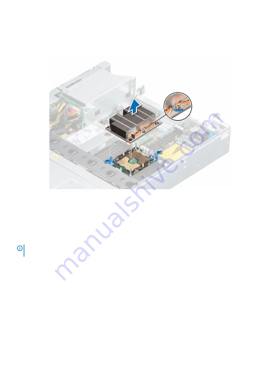
b) Loosen the second screw completely.
c) Return to the first screw and loosen it completely.
2. Pushing both blue retention clips simultaneously, lift the processor and heat sink module (PHM) processor and heat sink module.
3. Set the PHM aside with the processor side facing up.
Figure 60. Removing a processor and heat sink module
Next steps
Replace a processor and heat sink module
.
Removing the processor
Prerequisites
NOTE:
Only remove the processor from the processor and heat sink module if you are replacing the processor or heat
sink. This procedure is not required when replacing a system board.
1. Follow the safety guidelines listed in
2. Power off the system and all attached peripherals.
3. Disconnect the system from the electrical outlet, and disconnect the peripherals.
4.
5. Remove the
6. Remove the system from the rack and place it on an ESD work bench. For more information, see the
Rail Installation Guide
at
7.
.
8.
9. If installed,
10.
Remove a processor and heat sink module
.
Steps
1. Place the heat sink with the processor side facing up.
2. Insert a flat blade screwdriver into the release slot marked with a yellow label. Twist (do not pry) the screwdriver to break the thermal
grease seal.
80
Installing and removing system components


