Jumpers and Connectors
151
Table 6-2.
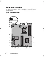
System Board Connectors
Item
Connector
Description
1
CPU2
Processor 2
2
iDRAC6 Enterprise
iDRAC6 Enterprise card connector
3
B4
B1
B2
B3
Memory module slot B4
Memory module slot B1 (white release lever)
Memory module slot B2 (white release lever)
Memory module slot B3 (white release lever)
4
CPU1
Processor 1
5
FAN1
Cooling fan 1 connector
6
FAN2
Cooling fan 2 connector
7
A3
A2
A1
A4
Memory module slot A3 (white release lever)
Memory module slot A2 (white release lever)
Memory module slot A1 (white release lever)
Memory module slot A4
8
FAN3
Cooling fan 3 connector
9
BATTERY
System battery
10
FAN4
Cooling fan 4 connector
11
12V
8-pin power connector
12
FP_CONN
control panel connector
13
BP_CONN
Backplane power connector
14
PWR_CONN
24-pin power connector
15
PDB_ I2C
Power distribution board connector
16
FP_USB_CONN
Backplane USB connector
17
SATA_A
SATA_B
SATA_C
SATA_D
SATA_E
SATA connector A
SATA connector B
SATA connector C
SATA connector D
SATA connector E
book.book Page 151 Friday, February 26, 2010 11:22 AM
Summary of Contents for DX6012S
Page 10: ...10 Contents ...
Page 40: ...40 About Your System ...
Page 62: ...66 Using the System Setup Program and UEFI Boot Manager ...
Page 118: ...122 Installing System Components ...
Page 134: ...144 Troubleshooting Your System ...
Page 144: ...154 Jumpers and Connectors ...
Page 146: ...156 Getting Help ...
Page 152: ...162 Index ...


