DeDietrich MODULENS O AFC 18 Installation And Service Manual Download Page 85

U

Connect the load pump.

Settings to be made for this type of installation
Parameters

Access

Settings to be made See chapter

INSTALLATION

Installer level

#SYSTEM

 menu

EXTENDED

¼

 "Displaying the parameters in

extended mode", page 102

If the electric tank is connected to 

M

A

:

CIRC.A

(1)

Installer level

#SYSTEM

 menu

DHW ELEC

¼

 "Setting the parameters specific to the

installation", page 102

If the electric tank is connected to

M

AUX

:

S.AUX

(1)

Installer level

#SYSTEM

 menu

DHW ELEC

(1) The parameter is only displayed if 

INSTALLATION

 parameter is set to 

EXTENDED

5.8.13.

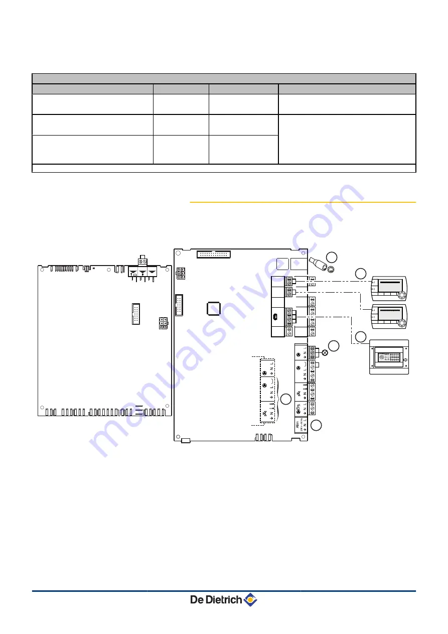
Connecting the options

For example: TELCOM remote vocal monitoring module, remote

controls for circuits 

A

 and 

B

, second DHW tank

On

/o

ff

OT

BL

SE

xt

PCU

SCU

T

+

C

A

U

X

C

C003151-D

T

+

B

A

B

0

-1

0

V

S

 AMB 

C

4


3


2


1

2


1

 -

S

 AM

B

2


1

S

 AM

A

2


1

SYST

T

A

 -

EC

S

EXT

D

EP

 C

2


1

2


1

2


1

2


1

2


1

D

EP

 B

2


1

MODE

r

x

0

2

4

6

8

10

12

14

16

18

22

24

20

c

MODE

r

x

0

2

4

6

8

10

12

14

16

18

22

24

20

c

V

PRG

TELCOM 2

ALP

AL2

AL1

3

2

1

SET

#

0

9

V

8

7

6

5

4

3

2

1

6

4

3

2

1

5

A

MODBUS cascade connection, VM

Z

Connect the remote control (Package AD254/FM52)).

E

Connect the TELCOM remote vocal monitoring module

(depending on its availability in your country).

R

Alarm indicator

T

Connect the load pump of the second tank.

Y

Do not connect anything to the terminal block.

AFC 18 - AFC 24 - AFC 30

5. Installation

09/07/2015 - 300026439-07

83

Summary of Contents for MODULENS O AFC 18

Page 1: ...Export MODULENS O EN Oil fired condensing boilers AFC 18 AFC 24 AFC 30 Installation and Service Manual 300026439 07 ...

Page 2: ... complies with the standard type described in the EG declaration of conformity It was manufactured and commissioned in accordance with European directives The original declaration of conformity is available from the manufacturer C003918 A ...

Page 3: ...ogations 11 3 1 1 Certifications 11 3 1 2 Oil category 11 3 1 3 Additional Directives 11 3 1 4 Factory test 12 3 2 Technical specifications 12 3 2 1 Boiler specifications 12 3 2 2 Burner specifications 14 3 2 3 Sensor characteristics 14 4 Product description 15 4 1 General description 15 4 2 Operating principle 15 4 2 1 Skeleton Diagrams 15 4 2 2 Circulation pump 20 4 2 3 Water flow rate 20 4 2 4 ...

Page 4: ... 6 Connecting the condensate discharge pipe 46 5 4 7 Filling the condensate trap 48 5 5 Oil connection 48 5 5 1 General 48 5 5 2 Connecting 49 5 5 3 Diameter and length of the oil pipes 49 5 6 Flue gas system connections Depending on country 50 5 6 1 Connections for the air and exhaust pipes Forced flow forced flue Type C 50 5 6 2 Connections for the air and exhaust pipes Single flow chimney Type ...

Page 5: ...e menus 97 6 2 Checks and settings before commissioning 98 6 2 1 Preparing the boiler for commissioning 98 6 3 Putting the appliance into operation 98 6 4 Setting the burner 99 6 4 1 Operations to be carried out before any attempt to set the burner 99 6 4 2 Setting the burner s 3 operating outputs 100 6 4 3 Checking combustion 101 6 5 Checks and adjustments after commissioning 102 6 5 1 Displaying...

Page 6: ...charge 132 8 4 3 Checking the automatic air vent 132 8 4 4 Cleaning of the heating body 133 8 4 5 Cleaning the siphon 137 8 4 6 Checking and replacing the installation s oil filter 138 8 4 7 Maintenance of the burner 138 8 5 Specific maintenance operations 142 8 5 1 Replacing the ignition electrodes 143 8 5 2 Maintenance of the air flue gas drain connection flues 144 9 Troubleshooting 145 9 1 Anti...

Page 7: ... Hydraulics 165 10 2 3 Expansion vessel 18 litres Depending on country standard delivery or optional 166 10 2 4 Casing 167 10 2 5 Control panel 168 10 2 6 Fuel oil burner Details 169 10 2 7 Spare parts list 170 11 Appendix Information on the Ecodesign and Energy Labelling Directives 174 09 07 2015 300026439 07 5 ...

Page 8: ...y children without supervision DANGER If you smell flue gases 1 Switch the appliance off 2 Open the windows 3 Trace possible leaks and seal them immediately WARNING Depending on the settings of the appliance 4 The temperature of the flue gas conduits may exceed 60 C 4 The temperature of the radiators may reach 95 C 4 The temperature of the domestic hot water may reach 80 C depending on the set poi...

Page 9: ...nt Keep this document close to the place where the boiler is installed Casing components Only remove the casing for maintenance and repair operations Put the casing back in place after maintenance and repair operations Instructions stickers The instructions and warnings affixed to the appliance must never be removed or covered and must remain legible during the entire lifespan of the appliance Imm...

Page 10: ...ficient maintenance of the appliance 4 Failure to abide by the instructions on installing the appliance 1 3 2 Installer s liability The installer is responsible for the installation and commissioning of the appliance The installer must respect the following instructions 4 Read and follow the instructions given in the manuals provided with the appliance 4 Carry out installation in compliance with t...

Page 11: ...k of a dangerous situation causing slight physical injury CAUTION Risk of material damage Signals important information Signals a referral to other instructions or other pages in the instructions 2 1 2 Symbols used on the equipment 4 Protective earthing Alternating current Before installing and commissioning the device read carefully the instruction manuals provided Dispose of the used products in...

Page 12: ...omestic hot water 4 Hi Lower heating value LHV Nett 4 Hs Higher heating value HHV Gross 4 HL High Load DHW tank with plate exchanger 4 SL Standard Load DHW tank with coil 4 SHL Solar High Load Solar DHW tank with plate exchanger 4 MC Boiler module 4 CFC Chlorofluorocarbon 2 3 After Sales Service Internet Site The QR code or flashcode is used to access the internet site containing the documentation...

Page 13: ... content 50 mg kg supplemented with 3 to 5 9 FAME in volume FAME is produced from vegetable oil or processed animal fat EMAG Fatty Acid Methyl Ester also called EMAG Ester Méthylique d Acide Gras 3 1 3 Additional Directives Apart from the legal provisions and Directives the additional Directives described in these instructions must also be observed For all provisions and Directives referred to in ...

Page 14: ...g temperature 85 C 4 Boiler temperature Adjustable from 30 to 90 C 4 Safety thermostat 105 C 4 Min flow temperature 20 C 4 Min return temperature 20 C 4 Ambient temperature 20 C Boiler AFC 18 AFC 24 AFC 30 Minimum power Full power Minimum power Full power Minimum power Full power Power input Hi kW 10 4 17 6 13 9 23 5 17 4 29 4 Nominal output Pn at 40 30 C kW 10 7 18 2 14 3 24 3 17 8 30 3 Nominal o...

Page 15: ...nal water flow rate at Pn 50 30 C ΔT 20K m3 h 0 773 1 032 1 291 Stand by losses ΔT 30K W 109 109 128 Percentage of losses through the walls compared with the stand by losses ΔT 30K 61 61 63 Loss of load hydraulic circuit Pn ΔT 10K mbar 2 66 0 117 0 183 0 ΔT 15K mbar 2 29 0 52 0 81 0 ΔT 20K mbar 2 16 0 29 0 46 0 Electrical power of the boiler only with no accessories W 128 272 128 272 128 272 Water...

Page 16: ...0 2 2 0 2 2 0 2 Max permitted pressure on blocking bar MPa 2 0 2 2 0 2 2 0 2 Max pump air flow at 10 bar 1 MPa l h 45 45 45 1 Power at an altitude of 400 m and at a temperature of 20 C Heating value of fuel oil LHV 11 86 kWh kg 2 Bio oil max B10 max viscosity 6 mm2 s at 20 C 3 2 3 Sensor characteristics Outside sensor Temperature in C 20 16 12 8 4 0 4 8 12 16 20 24 Resistance in Ω 2392 2088 1811 1...

Page 17: ...p of the range electronic DIEMATIC iSystem control panel 4 Flue gas discharge via a forced flue or chimney type connection 4 2 Operating principle 4 2 1 Skeleton Diagrams n Boiler self standing Circuit A 1 On Off switch 2 Control panel 3 Burner 4 Automatic air vent 5 Heating flow 6 Heating return 7 Heating body 8 Circulation pump 9 0 3 MPa safety valve 3 bar 10 Condensate trap 11 Flue gas discharg...

Page 18: ...rcuit 7 Heating body 8 Direct circuit circulating pump 9 0 3 MPa safety valve 3 bar 10 Condensate trap 11 Flue gas discharge 12 3 way valve 13 Heating return valve circuit 14 Heating flow valve circuit 15 Heating pump circuit mixing valve 16 Non return valve 12 C003131 i 4 5 6 3 8 9 7 13 14 15 11 10 2 1 16 16 4 Product description AFC 18 AFC 24 AFC 30 16 09 07 2015 300026439 07 ...

Page 19: ...Pa safety valve 3 bar 10 Condensate trap 11 Flue gas discharge 16 Non return valve 17 Domestic hot water outlet 18 Plate heat exchanger 19 Domestic hot water pump 20 Domestic hot water tank 21 Primary domestic hot water load pump 22 Domestic cold water inlet M002429 G 2 1 4 5 6 3 16 8 9 7 10 19 20 18 17 11 16 21 22 AFC 18 AFC 24 AFC 30 4 Product description 09 07 2015 300026439 07 17 ...

Page 20: ...ve 3 bar 11 Condensate trap 12 Calorifier load pump 13 Flue gas discharge 14 Domestic hot water tank 15 Domestic water coil 16 Manual bleed valve 17 Domestic cold water inlet 18 Domestic hot water outlet Configuration with a DHW tank also enables the connection of a circuit with mixing valve M002430 F 5 6 2 1 4 3 9 10 8 11 18 17 14 15 16 13 7 12 7 4 Product description AFC 18 AFC 24 AFC 30 18 09 0...

Page 21: ... 13 Flue gas discharge 14 Domestic water solar coil 15 Primary solar circuit filling and draining device 16 Solar expansion vessel 12 l 17 solar circulation pump 18 Domestic hot water tank 19 Antithermosiphon valve operated by the spherical plug valve 20 Degasser with manual purge to the solar circuit drain valve C003834 C 2 1 3 4 5 6 8 9 7 10 11 12 7 13 15 14 24 25 27 28 26 16 17 18 19 20 21 22 2...

Page 22: ... speed with the parameter MAX PUMP SPEED First of all vent the heating system If circulation in the radiators is too low or the radiators do not fully heat up increase the minimum pump speed with the parameter MIN PUMP SPEED See chapter Professional settings page 114 4 2 3 Water flow rate The boiler s modulating control system limits the maximum difference in temperature between the heating flow a...

Page 23: ...x 400 seconds C2 2 14 Pre ignition and preventilation time 15 seconds C3 2 15 Electro valve opening No flame presence Max time Safety time TS 5 seconds C4 2 16 Post ignition time 7 seconds C5 2 17 Flame stabilisation for 20 sec C6 x x Output modulation C7 5 41 Post ventilation 120 seconds AFC 18 AFC 24 AFC 30 4 Product description 09 07 2015 300026439 07 21 ...

Page 24: ...n Normal start up D D ITR C003259 E P Oil Arc 4 Product description AFC 18 AFC 24 AFC 30 22 09 07 2015 300026439 07 ...

Page 25: ...n Start up without flame detection D C003223 E D ITR P Oil Arc AFC 18 AFC 24 AFC 30 4 Product description 09 07 2015 300026439 07 23 ...

Page 26: ...n Loss of the flame signal whilst in operation M003249 B ITR Arc OV 1 0 1 C1 C7 C1 0 1 0 1 0 1 0 1 0 C2 C4 C4 C2 C3 C5 4 Product description AFC 18 AFC 24 AFC 30 24 09 07 2015 300026439 07 ...

Page 27: ... Electronic pressure sensor Pressure in the heating circuit 9 Modulating heating pump 10 Condensates evacuation pipe 11 Drain cock 12 0 3 MPa safety valve 3 bar 13 Condensate trap 14 Heating pump circuit mixing valve Option 15 Motorised 3 way mixing valve Option 16 Connection PCBs PCU SCU 17 Command module 18 On Off switch 19 Flue gas pressure switch C003129 G 5 6 7 17 18 16 8 9 13 14 19 15 11 10 ...

Page 28: ...lot 14 Burner pipe 15 Component plate 16 Modulating motor management box 17 Air enclosure 18 Air inlet 19 Fuel supply pipes 20 Door handle Flexible mounting flange 21 Connector 230 V 22 Filling line 23 Pre heater 24 Combustion head 25 air nozzle 26 Nozzle 27 Ignition electrode 4 4 Package list 4 4 1 Standard delivery The delivery includes 4 The assembled boiler with the burner 4 The oil filter the...

Page 29: ...sion vessel MV4 Flue gas system options Description package Chimney connection kit PPS diameter 80 110 mm DY876 Air flue gas terminal horizontal forced flue FM183 Air flue gas terminal vertical forced flue Black DY843 Red DY844 Back flue gas outlet kit MV9 Control system options Description package RX12 cable AD134 TELCOM2 voice remote monitoring module AD152 Flow sensor AD199 DHW sensor AD212 Opt...

Page 30: ...00HL MV7 Boiler DHW tank hydraulic connecting kit 160SL MV8 Boiler DHW tank hydraulic connecting kit 160SL HEE Class A pump MV32 Connecting kit for external DHW tank HEE Class A pump MV33 Boiler solar DHW tank hydraulic connecting kit 220SHL MV11 Boiler DHW tank hydraulic connecting kit MV18 4 Product description AFC 18 AFC 24 AFC 30 28 09 07 2015 300026439 07 ...

Page 31: ... operating on combustible gases and liquefied hydrocarbons Articles CH Heating ventilation refrigeration air conditioning and production of steam and domestic hot water Instructions specific to each type of establishment open to the public hospitals stores etc Germany Standards to be respected 4 FeuVo decree paragraph 3 4 DIN EN 12828 June 2003 edition heating systems in buildings Planning of hot ...

Page 32: ...identification no One nameplate is affixed to the back of the appliance Affix the nameplate provided in the document bag to the boiler casing where it can be seen 5 2 2 Positioning of the appliance CAUTION When installing the appliance respect the IP21 environmental rating 4 Place the appliance on a base frame to facilitate cleaning of the premises 4 Allow enough space around the appliance to faci...

Page 33: ...iler to install the following components 4 The heating circuit expansion vessel 4 The oil filter the deaerator the stop valve M002360 E 1700 min 500 320 min 250 A 500 1100 min 500 320 min 250 C 500 1100 min 500 320 685 min 250 A 500 C003133 B B DHW calorifier type Boiler model AFC 18 AFC 24 AFC 30 A mm 1130 1130 1200 B mm 100HL 160SL 921 921 921 220SHL 1201 1201 1201 C mm 100HL 1686 1686 1756 160S...

Page 34: ... boiler room is not necessary Condensing boilers require a flue gas discharge system or a fresh air inlet specially adapted to the method of operation Installation must be carried out in accordance with current laws CAUTION Do not block the air inlet combustion product evacuation or condensation water flow pipes even partially Avoid any low points in the flue gas and condensates discharge circuit ...

Page 35: ...e supply of fresh air must be provided as close as possible to the appliances Its cross section must be at least 0 5 dm 4 In the upper section of the premises an air outlet must ensure effective ventilation n Establishments open to the public 4 New establishment Refer to the order of 25 06 1980 installations of more than 20 kW and less than or equal to 70 kW 4 Existing establishment Refer to the o...

Page 36: ...iameter 80 mm o Concentric air flue gas connection diameter 80 125 mm 1 Adjustable feet 0 to 20 mm 2 If mounting the oil filter with deaerator inside the casing n Boiler self standing Models AFC 18 AFC 24 AFC 30 A mm 1130 1130 1200 B mm 1175 1175 1245 681 983 45 69 98 302 600 A B 472 1 410 160 83 346 607 1005 681 83 2 1 6 16 19 5 4 3 C003135 H 520 435 163 93 84 5 2 308 69 102 54 56 128 17 128 18 5...

Page 37: ...30 1200 B mm 1175 1175 1245 681 75 983 45 69 98 302 600 A B 472 1 2 1164 1240 640 300 584 1553 2 1 6 5 M002424 E 84 5 308 128 13 710 56 128 906 17 245 7040 10 11 16 19 12 18 M002427 E 681 45 69 98 983 302 1200 A 472 600 911 1 607 681 B 83 1005 2 1 5 6 84 5 308 2 78 300 870 245 69 12 16 19 13 10 11 520 435 163 93 69 128 160 56 54 17 346 126 18 AFC 18 AFC 24 AFC 30 5 Installation 09 07 2015 30002643...

Page 38: ...0 B mm 1175 1175 1245 5 3 Positioning the appliance CAUTION 4 Have 2 people available 4 Handle the appliance with gloves 5 3 1 Positioning the boiler on its own 1 Remove the packaging from the boiler but leave the shipping pallet in place 2 Remove the protective packaging The technical documentation is housed in the protective block The outside temperature sensor is housed in the protective block ...

Page 39: ...he control panel 4 Remove the front panel by pulling firmly from both sides 5 Close the door 6 Remove the front and back holding screws C003137 G 4 3 C003138 G 6 6 5 AFC 18 AFC 24 AFC 30 5 Installation 09 07 2015 300026439 07 37 ...

Page 40: ...in diameter and 1400 mm in length 8 Install the appliance on the base provided 9 Level the appliance using the adjustable feet 1 Adjustable feet Basic dimension 30 mm Can be adjusted from 20 mm to 40 mm 10 Refit the front panel 9 9 C003140 E 1 5 Installation AFC 18 AFC 24 AFC 30 38 09 07 2015 300026439 07 ...

Page 41: ...sport pallet using lifting bars Use steel tubes 3 4 in diameter and 1400 mm in length 4 Position the boiler on the DHW tank 5 Put the retaining screws in place 6 Refit the front panel 5 3 3 Positioning the boiler to the left or right of a DHW tank 1 Put the DHW tank in place Refer to the DHW tank s installation use and maintenance instructions 2 Put the boiler in place See chapter Positioning the ...

Page 42: ...the right proceed as follows 1 Open and remove the control panel door 2 Take the control system module out of its housing and disconnect it 3 Unscrew the mounting screws at the back of the top panel Boiler 18 kW 24 kW 2 screws Boiler 30 kW 3 screws Remove the top panel 1 C003099 D C003121 C 2 C003285 B 3 3 5 Installation AFC 18 AFC 24 AFC 30 40 09 07 2015 300026439 07 ...

Page 43: ...holding the front of the control unit 6 Pivot the holder by 180 7 Retighten the fastening screws on the control panel 8 Tilt the control panel C003160 F 4 5 5 4 C003161 C 180 6 6 C003162 E 8 7 7 AFC 18 AFC 24 AFC 30 5 Installation 09 07 2015 300026439 07 41 ...

Page 44: ...ace the top 10 Reconnect and put the control system module back in place 11 Refit the control panel door C003286 B 9 9 C003163 B 10 C003164 D 11 5 Installation AFC 18 AFC 24 AFC 30 42 09 07 2015 300026439 07 ...

Page 45: ... the system copper hemp flux 4 Thoroughly flush the installation until the water runs clear and shows no impurities n Fitting the appliance to existing installations 4 Remove sludge from the installation 4 Flush the installation 4 Clean the installation with a universal cleaner to eliminate debris from the system copper hemp flux 4 Thoroughly flush the installation until the water runs clear and s...

Page 46: ...l C003141 F 4 4 3 2 2 1 1 Fold back the precut stop pin in the back panel by 90 2 Insert the screws 3 Hook the support to the back of the boiler or to the wall according to the installation 4 Tighten the screws A Mounting the expansion vessel behind the boiler B Mounting the expansion vessel to the wall A B C003142 E 5 Installation AFC 18 AFC 24 AFC 30 44 09 07 2015 300026439 07 ...

Page 47: ...st be avoided at all costs We recommend mounting the deaerator outside the boiler A If circumstances do not allow this it is possible to mount the deaerator inside the boiler B B A C003144 F 30 kW 18 kW 24 kW FloCo Top FloCo Top A Mounting the deaerator outside the boiler B Mounting the deaerator inside the boiler E Marking on the hose intended for connection of the oil supply CAUTION Connect the ...

Page 48: ...all a T piece fitted with a 1 4 turn valve on the heating return circuit to fill the circuit 4 A disconnector must be installed for filling the heating circuit in accordance with the regulations in force 5 4 5 Connection of the water circuit for domestic use If need be refer to the DHW tank s installation user and maintenance manual 5 4 6 Connecting the condensate discharge pipe Discharge the cond...

Page 49: ...ow through the siphon to the wastewater network 3 Mount a trap or a siphon in the discharge pipe CAUTION Do not make a permanent rigid connection owing to maintenance work on the condensate trap 4 The condensate drain must be connected openly to the drain 4 Set the discharge pipe at a gradient of at least 30 mm per metre maximum horizontal length 5 metres 4 Do not drain condensation water into a r...

Page 50: ... 5 Oil connection 5 5 1 General 4 Use a single pipe system and mount the oil filter with the deaerator and the stop valve provided with the boiler The negative pressure required for the oil supply must be less than 0 35 bar 0 035 MPa 4 Use of a floating strainer is strongly recommended to prevent deposits being sucked up from the bottom of the tank 4 If replacing the boiler clean the tank C003257 ...

Page 51: ...on pipe between the cistern and the filter E Oil suction strainer R Oil flow hose from the burner T Oil return hose to the burner Y Fuel oil burner U Oil cistern 5 5 2 Connecting 1 Connect the oil supply pipe to the deaerator filter 5 5 3 Diameter and length of the oil pipes Refer to the instructions delivered with the package FloCo Top C003277 F 3 7 2 2 4 5 4 5 1 6 C003271 C 1 AFC 18 AFC 24 AFC 3...

Page 52: ...k is even higher when the length of the flue gas connection pipe to the wall or chimney is significant The horizontal flue gas pipes must be installed with a minimum gradient of 1 to allow the flow of the condensates that form in the pipes to the boiler siphon 5 6 1 Connections for the air and exhaust pipes Forced flow forced flue Type C When it leaves the factory the connection configuration of t...

Page 53: ...UTION The maximum lengths Lmax given in the table are valid for pipes on which the horizontatal sections do not exceed one metre in total For each additional metre of horizontal pipe a multiplication coefficient of 1 2 must be applied when calculating the total length L The total length L is calculated by adding the lengths of the straight air flue gas pipes and the equivalent lengths of the other...

Page 54: ...ressure combustive air taken from the boiler room 2 Configuration B23P Top outlet Connection to a chimney under pressure combustive air taken from the boiler room 3 Configuration B23P Bottom outlet Connection to a chimney under pressure combustive air taken from the boiler room WARNING 4 Only factory components are authorised for connecting the boiler and the terminal 4 The clear section must comp...

Page 55: ... at 87 R Support rail U DN80 extension Length 0 5 m Options T Ventilation grate Y Sleeve Diameter 124 Length 0 5 m DY753 I Closing plate DY757 O DN80 extension P Boiler n Flexible B23 and B23P type connection Use package DY895 M001872 B x mini DY717 1 2 2 3 6 7 8 9 10 5 L 4 3 AFC 18 AFC 24 AFC 30 5 Installation 09 07 2015 300026439 07 53 ...

Page 56: ...ow at 87 R Support rail U DN80 extension Length 0 5 m Options T Ventilation grate Y Sleeve Diameter 124 Length 0 5 m DY753 I Closing plate DY757 O DN80 extension P Boiler M003162 B DY897 10 3 DY895 1 2 2 2 5 4 3 6 7 8 9 5 Installation AFC 18 AFC 24 AFC 30 54 09 07 2015 300026439 07 ...

Page 57: ... the lengths of the straight air flue gas pipes and the equivalent lengths of the other components Lmax m Configuration B23P AFC 18 AFC 24 AFC 30 Diameter 80 mm rigid 18 18 18 Diameter 80 mm Flexible 15 15 15 Equivalent length of PPS pipes m internal Ø 80 mm Elbow at 87 1 9 Elbow at 45 1 2 Right inspection tube 0 3 87 inspection elbow 1 9 WARNING Always ensure that L is less than Lmax For the list...

Page 58: ...m 1 Open the access door on the control panel 2 Remove the access door from the control panel 3 Remove the front panel by pulling firmly from both sides 4 Unscrew the mounting screws at the back of the top panel 18 kW 24 kW 2 screws 30 kW 3 screws Remove the top panel 5 Unclip the control panel C003154 F 3 1 2 C003155 F 4 4 5 5 5 Installation AFC 18 AFC 24 AFC 30 56 09 07 2015 300026439 07 ...

Page 59: ... the instructions delivered with the package MV9 5 7 Installing the outside sensor 5 7 1 Choice of the location It is important to select a place that allows the sensor to measure the outside conditions correctly and effectively Advised positions 4 on one face of the area to be heated on the north if possible 4 half way up the wall in the room to be heated 4 under the influence of meteorological v...

Page 60: ...ny roof etc 4 close to a disruptive heat source sun chimney ventilation grid etc 5 7 2 Connecting the outside sensor Mount the sensor using the screws and dowels provided A Inserts Z Ø4 wood screw For the connection of the outside temperature sensor refer to the chapter Electrical Connections 8800N001 C 8800N002 C 8800N003 C 2 5 Installation AFC 18 AFC 24 AFC 30 58 09 07 2015 300026439 07 ...

Page 61: ...ith a gap of more than 3 mm Single phase power supply 230 V 6 10 50 Hz Power supply cable premounted Connect the boiler to a 6 amp circuit breaker Type C CAUTION Keep to the polarity shown on the terminals phase L neutral N and earth A Routing of the 230 V cables Z Routing of the sensor cables CAUTION Disconnect the power supply at the mains before carrying out any work on the appliance or accesso...

Page 62: ... standards CAUTION Separate the sensor cables from the 230 V cables In the boiler use the 2 ducts located on the right hand side of the boiler for this purpose All connections are made to the terminal blocks provided for this purpose in the boiler connection box The connection cables are fed into the boiler by means of two connection ducts located in the right side panel The available output per o...

Page 63: ...oiler on its own page 36 1 Lift the tab 2 Remove the protective cover The connections must be made according to the details given below C003148 E 1 2 PCU SCU AFC 18 AFC 24 AFC 30 5 Installation 09 07 2015 300026439 07 61 ...

Page 64: ...ty thermostat to the connector Z Do not connect anything to the terminal block E Connect the outside temperature sensor Settings to be made for this type of installation Parameters Access Settings to be made See chapter INSTALLATION Installer level SYSTEM menu EXTENDED Displaying the parameters in extended mode page 102 If safety thermostat is connected to BL on the connection terminal block IN BL...

Page 65: ...9 F M A Connect a safety thermostat if the heating circuit is for underfloor heating 4 Remove the bridge 4 Connect the wires from the safety thermostat to the connector Z Do not connect anything to the terminal block E Flow sensor circuit B R Connect the outside temperature sensor T Limiting thermostat 3WV circuit circuit B Y Pump 3WV circuit circuit B U 3 way valve circuit B AFC 18 AFC 24 AFC 30 ...

Page 66: ...ON Installer level SYSTEM menu EXTENDED Displaying the parameters in extended mode page 102 If safety thermostat is connected to BL on the connection terminal block IN BL Installer level PRIMARY INSTAL P menu STOP HEAT Professional settings page 114 5 Installation AFC 18 AFC 24 AFC 30 64 09 07 2015 300026439 07 ...

Page 67: ...ST TA S ECS S EXT S DEP C 2 1 2 1 2 1 2 1 2 1 S DEP B 2 1 C003288 F 1 5 6 3 3 2 4 7 8 9 10 11 3 A Connect a safety thermostat if the heating circuit is for underfloor heating 4 Remove the bridge 4 Connect the wires from the safety thermostat to the connector Z Plate exchanger outlet sensor E Do not connect anything to the terminal block R Secondary domestic hot water load pump AFC 18 AFC 24 AFC 30...

Page 68: ...aller level SYSTEM menu EXTENDED Displaying the parameters in extended mode page 102 If a domestic hot water looping pump is connected to MA on the terminal block O PUMP A 1 Installer level SYSTEM menu DHW LOOP Setting the parameters specific to the installation page 102 If safety thermostat is connected to BL on the connection terminal block IN BL Installer level PRIMARY INSTAL P menu TOTAL STOP ...

Page 69: ...nect a safety thermostat if the heating circuit is for underfloor heating 4 Remove the bridge 4 Connect the wires from the safety thermostat to the connector Z Do not connect anything to the terminal block E Connect the outside temperature sensor R Connect the DHW sensor T Connect the DHW tank anode Y Connect the domestic hot water looping pump Option U Connect the load pump Option AFC 18 AFC 24 A...

Page 70: ...stat is connected to BL on the connection terminal block IN BL Installer level PRIMARY INSTAL P menu TOTAL STOP Professional settings page 114 1 The parameter is only displayed if INSTALLATION parameter is set to EXTENDED 5 8 7 Connecting a direct heating circuit and an independent domestic hot water tank On off OT BL SExt PCU DHW X20 SCU TS B A B 0 10V S AMB C 4 3 2 1 2 1 S AMB B 2 1 S AMB A 2 1 ...

Page 71: ...e delivered with the DHW sensor package AD212 U Connect the load pump Settings to be made for this type of installation Parameters Access Settings to be made See chapter INSTALLATION Installer level SYSTEM menu EXTENDED Displaying the parameters in extended mode page 102 If a domestic hot water looping pump is connected to MA on the terminal block O PUMP A 1 Installer level SYSTEM menu DHW LOOP Se...

Page 72: ...domestic hot water looping pump to the MA outlet Z Do not connect anything to the terminal block E Connect the DHW sensor Package AD212 R Connect a safety thermostat if the heating circuit is for underfloor heating 4 Remove the bridge 4 Connect the wires from the safety thermostat to the connector T Connect the 3 way valve flow sensor circuit B Y Connect the heating pump circuit B U Connect the 3 ...

Page 73: ...Connecting an additional C circuit to the AD249 option Settings to be made for this type of installation Parameters Access Settings to be made See chapter INSTALLATION Installer level SYSTEM menu EXTENDED Displaying the parameters in extended mode page 102 If a domestic hot water looping pump is connected to MA on the terminal block O PUMP A 1 Installer level SYSTEM menu DHW LOOP Setting the param...

Page 74: ... 2 5 5 13 11 6 7 8 12 10 9 5 14 C004456 B A Connect a safety thermostat if the heating circuit is for underfloor heating 4 Remove the bridge 4 Connect the wires from the safety thermostat to the connector Z Connect the 3 way valve flow sensor circuit B E Connect the heating pump circuit B R Connect the 3 way valve circuit B T Do not connect anything to the terminal block 5 Installation AFC 18 AFC ...

Page 75: ...Parameters Access Settings to be made See chapter INSTALLATION Installer level SYSTEM menu EXTENDED Displaying the parameters in extended mode page 102 BOILER PUMP Installer level SYSTEM menu ALL Setting the parameters specific to the installation page 102 If a domestic hot water looping pump is connected to MAUX on the terminal block S AUX Installer level SYSTEM menu DHW LOOP Setting the paramete...

Page 76: ...ation to the solar collectors Z Solar sensor probe E Do not connect anything to the terminal block R Connect the heating pump Circuit A T Buffer tank Y Connect the DHW sensor Package AD212 U Connect the outside temperature sensor I Connect the DHW tank anode If the tank is not fitted with an impressed current anode put the simulation connector in place delivered with the DHW sensor package AD212 O...

Page 77: ... Installer level SYSTEM menu ALL 1 The parameter is only displayed if INSTALLATION parameter is set to EXTENDED The DHW part is maintained at the DHW set point by the boiler The heating zone is maintained at the set temperature calculated according to the outside temperature The zone is reheated when the heating buffer temperature sensor O falls 6 C below the calculated set temperature Reheating i...

Page 78: ... domestic hot water tank if the storage tank U is only used for heating Z Connect the DHW sensor Package AD212 E Connect the load pump R Do not connect anything to the terminal block T Connect the heating pump Circuit A Y Connect the sensor from the storage tank U Buffer tank I Connect the solar station to the solar collectors O Solar sensor probe P Connect the outside temperature sensor 5 Install...

Page 79: ...aller level SYSTEM menu HEAT 1 The parameter is only displayed if INSTALLATION parameter is set to EXTENDED The DHW part is maintained at the DHW set point by the boiler The heating zone is maintained at the set temperature calculated according to the outside temperature The zone is reheated when the heating buffer temperature sensor falls 6 C below the calculated set temperature Reheating in the ...

Page 80: ...2 2 A Connect the heating pump Circuit A Z Do not connect anything to the terminal block E D H W load pump R Hot water storage tank sensor T Buffer tank Y Solar sensor probe U Connect the solar station to the solar collectors I Domestic hot water boiler O Connect the DHW sensor P Connect the outside temperature sensor 5 Installation AFC 18 AFC 24 AFC 30 78 09 07 2015 300026439 07 ...

Page 81: ...level SYSTEM menu HEAT 1 The parameter is only displayed if INSTALLATION parameter is set to EXTENDED The DHW tank is loaded from the storage tank If during DHW loading the temperature of the storage tank falls below the primary DHW set point parameter PRIM TEMP DHW the boiler maintains the latter at temperature to guarantee the loading of the DHW tank The heating zone is maintained at the set tem...

Page 82: ...ect anything to the terminal block E Connect the swimming pool sensor R Plate heat exchanger T Connect the primary swimming pool pump Y Pool heating cut off control When the parameter I TEL is on 0 1 B the swimming pool is no longer heated when the contact is open factory setting only the antifreeze continues to be active The contact direction can still be adjusted by the parameter CT TEL 5 Instal...

Page 83: ...ature MAX CIRC B is then guaranteed during comfort periods on programme B in summer and winter alike 4 Connect the swimming pool sensor package AD212 to the S DEP B inlet on the connection terminal block 4 Set the set point of the pool sensor using key C in the range 5 39 C Case 2 The pool has already a regulation system that is to be kept The control system only regulates the primary circuit boil...

Page 84: ...k is not fitted with an impressed current anode put the simulation connector in place delivered with the DHW sensor package AD212 T Outlet circuit A Option of connecting the electric tank or to Y Y Option of connecting the electric tank with AD249 option or to T On off OT BL SExt PCU SCU TS B A B 0 10V S AMB C 4 3 2 1 2 1 S AMB B 2 1 S AMB A 2 1 S SYST TA S ECS S EXT S DEP C 2 1 2 1 2 1 2 1 2 1 S ...

Page 85: ...xample TELCOM remote vocal monitoring module remote controls for circuits A and B second DHW tank On off OT BL SExt PCU SCU TS C AUX C C003151 D TS B A B 0 10V S AMB C 4 3 2 1 2 1 S AMB B 2 1 S AMB A 2 1 S SYST TA S ECS S EXT S DEP C 2 1 2 1 2 1 2 1 2 1 S DEP B 2 1 MODE r x 0 2 4 6 8 10 12 14 16 18 22 24 20 c MODE r x 0 2 4 6 8 10 12 14 16 18 22 24 20 c V PRG TELCOM 2 ALP AL2 AL1 3 2 1 SET 0 9 V 8...

Page 86: ... tank connected S AUX 1 Installer level SYSTEM menu DHW 1 The parameter is only displayed if INSTALLATION parameter is set to EXTENDED 5 8 14 Connection in cascade n DHW tank after the mixing tank A Master boiler Z Secondary boiler E Secondary boiler R D H W load pump T Connect the DHW sensor Package AD212 Y Cable BUS U Low loss header I Cascade outlet sensor Connect the sensor to the terminal blo...

Page 87: ...ttings to be made for this type of installation Follower boilers Parameters Access Settings to be made See chapter INSTALLATION Installer level SYSTEM menu EXTENDED Displaying the parameters in extended mode page 102 CASCADE 1 Installer level NETWORK menu ON Configuring the network page 122 MASTER CONTROLER 1 Installer level NETWORK menu OFF SLAVE NUMBER 1 Installer level NETWORK menu 2 3 1 The pa...

Page 88: ...RIMAIRE NULLEITER NEUTRE PHASE PHASE LEITERPLATTE STECKER SCU PCU CONNECTEUR CIRCUIT IMPRIME SCU PCU SNITTSTELLE MENCH MACHINE INTERFACE HOMME MACHINE BRENNER BRULEUR KESSELKREISPUMPE KREIS A ACCELERATEUR CIRCUIT A SPEICHERLADEPUMPE POMPE DE CHARGE ECS EINTRITT ENTREE ALGEMENE SCHAKELAAR MAIN SWITCH HOOG BEGRENZINGSTHERMOSTAAT H L HIGH LIMITER THERMOSTAT H L ROOKGASENTHERMOSTAAT FLUE GAS T LIMITER...

Page 89: ...AMB A Room sensor Circuit A SONDE AMB B Room sensor Circuit B SONDE AMB C Room sensor Circuit C SONDE DEP B Flow sensor Circuit B SONDE DEP C Flow sensor Circuit C SONDE ECS Domestic hot water sensor SONDE EXT Outside sensor SONDE SYST System sensor V3V 3 way valve SONDE DHW In Domestic cold water sensor SPL1 Splice X PCB connector X111 SU bus connector X112 Water pressure gauge X113 Flue gas limi...

Page 90: ...nd and safety box A2 Modulating motor management box B1 Flame detector B2 Pressure sensor B3 Electric filter E1 Pre heater F1 Boiler F2 Burner M1 Modulating motor T11 Ignition transformer X1 Wieland3 pole connector 230 V main supply X2 6 pole connector Control Y1 Modulating oil pump 5 Installation AFC 18 AFC 24 AFC 30 88 09 07 2015 300026439 07 ...

Page 91: ...al heating installation with at least 3x the volume of the central heating installation Flush the DHW pipes with at least 20 times the volume of the pipes For an optimum functioning of the boiler the water of the installation must comply with following characteristics Total installed heat output kW 70 Degree of acidity water non treated pH 6 5 8 5 Degree of acidity water treated pH 7 9 Conductivit...

Page 92: ...pen the valves on all radiators connected to the heating system 4 Remove the upper panel from the boiler 4 Disconnect the power supply cable to the burner 4 Connect the filling tube to a cold water tap 4 Fill the tank slowly to facilitate bleeding D000017 B 1 2 3 4 T000149 A C003302 B 9 C003298 A 5 Installation AFC 18 AFC 24 AFC 30 90 09 07 2015 300026439 07 ...

Page 93: ... to accelerate venting 4 To access user level Press the key 4 Select the MEASURES menu and then the PRESSURE parameter 4 Close the water tap when the water pressure reaches 2 bar 0 2 MPa 4 Bleed the radiators 4 Top up the water pressure in the circuit 4 Switch off the boiler electrical power supply 4 Reconnect the power supply cable to the burner and put the top panel back in place 4 Reset the com...

Page 94: ...the installer E Keys on which the function varies as and when selections are made F Rotary setting button 4 Turn the rotary button to scroll through the menus or modify a value 4 Press the rotary button to access the selected menu or confirm a value modification A000866 A bar STD t 0 2 4 6 8 10 12 14 16 18 22 24 20 pb AUTOxc r j M g m A B C D E F 6 Commissioning AFC 18 AFC 24 AFC 30 92 09 07 2015 ...

Page 95: ...rammed j Back to the previous level ESC Back to the previous level without saving the modifications made t Manual reset n Flame output level C002705 A The whole symbol flashes The burner starts up but the flame is not yet present C002704 A Part of the symbol flashes Output is increasing C002703 A Steady symbol The required output has been reached C002702 A Part of the symbol flashes Output is drop...

Page 96: ...ivated 4 Flashing symbol Temporary override 4 Steady symbol Permanent override m Reduced mode The symbol is displayed when a NIGHT override reduced is activated 4 Flashing symbol Temporary override 4 Steady symbol Permanent override g Holiday mode The symbol is displayed when a HOLIDAY override antifreeze is activated 4 Flashing symbol Holiday mode programmed 4 Steady symbol Holiday mode active m ...

Page 97: ... Steady bar Permanent override n Other information r The symbol is displayed when domestic hot water production is running w Valve indicator The symbol is displayed when a 3 way valve is connected 4 x 3 way valve opens 4 c 3 way valve closes M The symbol is displayed when the pump is operating Name of the circuit for which the parameters are displayed bar STD t 0 2 4 6 8 10 12 14 16 18 22 24 20 C0...

Page 98: ...he key It is also possible to access the installer level by pressing only the key for around 5 seconds bar 1 1 2 2 r c STD t v 0 2 4 6 8 10 12 14 16 18 22 24 20 pb AUTOxc r j M g m SUNDAY 11 45 C002219 D 04 bar 1 1 2 2 r c STD t v 0 2 4 6 8 10 12 14 16 18 22 24 20 pb AUTOxc r j M g m SUNDAY 11 45 C002219 D 04 1 1 2 2 r c STD t v 0 2 4 6 8 10 12 14 16 18 22 24 20 pb AUTOxc r j M g m SUNDAY 11 45 TE...

Page 99: ...parameter turn the rotary button 4 To modify the parameter press the rotary button To go back to the previous display press the key j bar 1 1 2 2 r c STD t v 0 2 4 6 8 10 12 14 16 18 22 24 20 pb AUTOxc r j M g m SUNDAY 11 45 C002219 D 04 1 1 2 2 r c STD t v 0 2 4 6 8 10 12 14 16 18 22 24 20 pb AUTOxc r j M g m SUNDAY 11 45 5 TEMP 68 C002235 F 04 bar 1 1 2 2 r c STD t v 0 2 4 6 8 10 12 14 16 18 22 ...

Page 100: ...r the presence of an earth connection and its earth circuit 4 Check that the condensates can flow freely 6 3 Putting the appliance into operation WARNING Initial commissioning must be done by a qualified professional 1 Open the oil inlet 2 Deblock the circulating pumps if necessary Unscrew the guard plug at the front of the circulation pump Insert a screwdriver into the slot in the circulation pum...

Page 101: ...formation is shown on the display Check the mains supply voltage Check the connection of the power cable to the connector X1 on the PCU PCB 4 If there is a problem the error is displayed on the screen See chapter Messages Code type Bxx or Mxx page 145 See chapter Faults Code type Lxx or Dxx page 148 If a DHW sensor is connected and the antilegionella function is activated the boiler starts to heat...

Page 102: ...on To change the values proceed as for setting the air flow rates 7 Confirm by pressing the rotary setting button Factory setting values See table below To set the output it is necessary to limit oneself to setting the U value fan rotation speed If the CO2 value cannot be reached reduce the oil pressure value 8 To exit this menu press the j key Factory setting values Burner model Boiler power Outp...

Page 103: ...arge flue To do this proceed as follows 1 Unscrew the plug of the flue gas measurement point 2 Connect the flue gas analyser CAUTION Ensure that the opening around the sensor is completely sealed when taking measurements 3 Measure the CO2 level in the flue gases 4 Fill in the table below with the values measured Measured values P bar U CO2 Minimum output Start up output Maximum output 5 If the CO2...

Page 104: ...RADITIONAL Displays the parameters of a conventional installation TRADITIONAL EXTENDED Displays all parameters Regardless of what is done to the keys the regulator switches back to TRADITIONAL mode after 30 minutes 6 5 2 Setting the parameters specific to the installation 1 Access the installer level Press key for around 5 seconds 2 Select the menu SYSTEM 4 Turn the rotary button to scroll through...

Page 105: ...functions of the S AUX parameter without adding the PCB sensor option Package AD249 DHW LOOP Used to control the domestic hot water looping pump according to the DHW timer programme and force its operation during an override PRIMARY PUMP The outlet MA is active if a heating demand is present on the secondary pump ORDER BURNER The outlet MA is active when a burner demand is present FAILURE The outl...

Page 106: ...sor of a cascade system SYSTEM BUFFER TANK Hot water storage tank affected to heating only DHW STRAT Using the DHW tank with 2 sensors top and bottom ST TANK DHW Hot water storage tank affected to heating and domestic hot water O TEL 1 FAILURE The telephone outlet is closed in the event of failure FAILURE REVISION The telephone outlet is closed in the event of revision display DEF REV The telephon...

Page 107: ... 0 1 C DHW ON or OFF contact Enables use of the board s telephone inlet as an antifreeze activation inlet on circuit I TEL and DHW 0 1 A C DHW ON or OFF contact Enables use of the board s telephone inlet as an antifreeze activation inlet on circuit I TEL and DHW 0 1 B C DHW ON or OFF contact Enables use of the board s telephone inlet as an antifreeze activation inlet on circuit I TEL and DHW 0 1 A...

Page 108: ...to BOILER MAX 4 The MAUX outlet on the connection terminal block is not active 4 The boiler operates with a setpoint temperature as a function of the outside temperature Open ANTIFR The mode selected on the boiler is active The antifreeze mode is active on all boiler circuits 0 1 A The antifreeze mode is active on the circuit concerned The mode selected on the circuit is active 0 1 B The antifreez...

Page 109: ...alue modification For a detailed explanation of menu browsing refer to the chapter Browsing in the menus page 97 3 Select the circuit or generator you wish to rename Installer level NAMES OF THE CIRCUITS Menu Parameter Description Name given by the customer CIRC A Circuit A CIRC B Circuit B CIRC C Circuit C CIRC AUX Auxiliary circuit CIRC DHW Domestic hot water circuit GENE Generator 4 Turn the ro...

Page 110: ...apter Browsing in the menus page 97 3 Select the parameter CIRC CURVE 4 To modify the value directly turn the rotary button To modify the value by displaying the curve press key f bar 1 1 2 2 r c STD t v 0 2 4 6 8 10 12 14 16 18 22 24 20 pb AUTOxc r j L g m CIRC B FLOOR1 Personalize the nameof this circuit B a X Y Z C002345 D 04 1 1 2 2 r c STD t v 0 2 4 6 8 10 12 14 16 18 22 24 20 pb AUTOxc r j M...

Page 111: ...um operating temperature to be imposed on the heating circuit this temperature may be constant if the circuit gradient is nil A Maximum temperature of the circuit Z Water temperature in the circuit for an outside temperature of 0 C E DAY set point on the circuit R Outside temperature for which the maximum water temperature in the circuit is reached T Value of the heating curve This value correspon...

Page 112: ... other systems and situations the parameters can be modified 6 6 Reading out measured values The various values measured by the appliance are displayed in the MEASURES menu 1 To access user level Press the key 2 Select the menu MEASURES 4 Turn the rotary button to scroll through the menus 4 Press the rotary button to access the selected menu For a detailed explanation of menu browsing refer to the...

Page 113: ...y accumulated in the tank kWh BACK TEMP Temperature of the boiler return water C POWER Instantaneous boiler output 0 Burner off or running at minimum output HEATCONS 2 Energy consumed by the boiler in heating mode kWh DHW CONS 2 Energy consumed by the boiler in DHW mode kWh POWER KW Instant boiler output kW NB IMPULS Number of burner starts not restartable The meter is incremented by 8 every 8 sta...

Page 114: ... NEDERLANDS Display in Dutch POLSKI Display in Polish PУCCKИЙ Display in Russian TÜRK Display in Turkish 6 7 2 Calibrating the sensors 1 To access user level Press the key 2 Select the menu SETTING 4 Turn the rotary button to scroll through the menus or modify a value 4 Press the rotary button to access the selected menu or confirm a value modification For a detailed explanation of menu browsing r...

Page 115: ...oom temperature has stabilised Room temperature of circuit B OFFSET ROOM B 3 4 1 5 0 to 5 0 C Room offset on circuit B Is used to set a room offset Make this setting 2 hours after switching on when the room temperature has stabilised 0 0 ANTIFR ROOM B 4 0 5 to 20 C Room temperature at which the antifreeze mode is activated on circuit B 6 C CALIBR ROOM C 4 1 2 Calibration of the room sensor on circ...

Page 116: ...ircuit C MAX CIRC page 118 50 C OUT ANTIFREEZE OFF 8 to 10 C Outside temperature at which the installation s antifreeze protection is activated Below this temperature the pumps are permanently on and the minimum temperatures for each circuit are respected When NIGHT STOP is set the reduced temperature is maintained in each circuit SECONDARY INSTAL P menu OFF Antifreeze protection is not activated ...

Page 117: ...to 10 50 hours Characterisation of building s inertia 0 for a building with low thermal inertia 3 for a building with normal thermal inertia 10 for a building with high thermal inertia Modification of the factory setting is only useful in exceptional cases 3 22 hours CIRC CURVE A 2 0 to 4 Heating curve of the circuit A CIRC CURVE page 118 1 5 ANTICIP A 1 NO 0 0 to 10 0 Activation and adjustment of...

Page 118: ...tput 100 C 80 BAND WIDTH 2 4 to 16 K Control unit bandwidth for the 3 way valves Option of increasing the bandwidth if the valves are rapid or of reducing it if they are slow 12 K BOIL 3WV SHIFT 2 0 to 16 K Minimum temperature difference between the boiler and the valves 4 K H PUMP DELAY 2 0 to 15 minutes Timing of the shutdown of the heating pumps The timing of heating pump shutdown prevents the ...

Page 119: ...legionella running time 60 minutes Increment 30 minutes OPTIM DHW 6 OFF The function is deactivated OFF BOILER T When in heating mode the boiler temperature exceeds PRIM TEMP DHW by 3 C and DHW tank needs are not met the domestic hot water load pump starts TEMP SYST When in heating mode the system temperature exceeds PRIM TEMP DHW by 3 C and DHW tank needs are not met the domestic hot water pump s...

Page 120: ...0 Minimum speed of the solar pump 50 TUBE COLLECTOR YES NO Set to YES if tubular collectors are used NO MAX FLOW 0 to 20 l min Maximum flow rate of the solar pump MAX FLOW page 121 6 7 l mim 1 The menu is only displayed if the solar control system is connected and the INSTALLATION parameter is set to EXTENDED n MAX CIRC WARNING If using underfloor heating do not modify the factory setting 50 C To ...

Page 121: ...timized if a room sensor is connected The regulator will automatically fine set the anticipation time This function is dependent on the surplus power available in the installation n SCREED DRYING Used to force a constant flow temperature or a train to accelerate screed drying on underfloor heating The setting for these temperatures must follow the screed layer s recommendations The activation of t...

Page 122: ...uits without a room sensor 4 NIGHT DEC Reduced The reduced temperature is maintained during reduced periods The circuit pump operates constantly 4 NIGHT STOP Stop Heating is shut down during reduced periods When installation antifreeze is active the reduced temperature is maintained during reduced periods For circuits with a room sensor 4 When the room temperature is lower than the room sensor set...

Page 123: ...ut and a secondary boiler circuit the external regulator providing this 0 10 V power supply must always request a temperature at least equal to the needs of the secondary circuit n MAX FLOW In order for the regulator to calculate the quantity of heat produced by the installation parameter kWh input parameter MAX FLOW The parameter MAX FLOW is equal to the flow in litres per minute in the solar cir...

Page 124: ...em in cascade page 124 MASTER CONTROLER 3 ON NO Configure this control system as master on the bus ON SYSTEM NETWORK 4 Specific menu Enlist generators or VMs in cascade mode See chapter Connecting VM iSystem in cascade page 124 FUNCT 4 TRADITIONAL Operation in cascade Successive tripping of the various generators in the cascade according to needs TRADITIONAL PARALLEL Functioning in parallel cascad...

Page 125: ...evel SETTING Menu Parameter Adjustment range Description Factory setting Customer setting PERMUT 1 AUTO 1 10 This parameter is used to set the master boiler 4 AUTO The master boiler switches automatically every 7 days 4 1 10 The master boiler is always the one defined by this value AUTO 1 The parameter is only displayed if CASCADE is on ON and MASTER CONTROLER on ON n Connecting appliances in casc...

Page 126: ...ic menu 2 The screen displayed is used to select the numbers of the slave VMs to be added to the network Numbers 20 to 39 are dedicated to the VMs Turn the rotary button to scroll through the numbers and press to confirm the number chosen Press j to go back to the previous list 3 To remove a slave VM from the network select ERASE VM 4 The screen displayed is used to select the numbers of the slave...

Page 127: ...ESET of the generator sensors connected ROOM SENSOR Performs a RESET of the room sensors connected After reset TOTAL RESET and RESET EXCEPT PROG the control system goes back to the display of the language choice after a few seconds 1 Select the desired language by turning the rotary button 2 To confirm press the rotary button bar 1 1 2 2 r c STD t v 0 2 4 6 8 10 12 14 16 18 22 24 20 pb AUTOxc r j ...

Page 128: ...em starts up This protection functions as follows 4 If the water temperature is lower than 7 C the heating pump starts up 4 If the water temperature is lower than 4 C the boiler starts up 4 If the water temperature is higher than 10 C the boiler shuts down and the circulation pump continues to run for a short time 4 If the water temperature in the storage tank is less than 4 C it is reheated to it...

Page 129: ...ater tank if the tank temperature is lower than 4 C the water is reheated to 10 C To configure the holidays mode Refer to the user instructions AFC 18 AFC 24 AFC 30 7 Switching off the appliance 09 07 2015 300026439 07 127 ...

Page 130: ...ce operations page 131 4 Carry out specific maintenance operations if necessary See chapter Specific maintenance operations page 142 8 2 Chimney sweep instructions CAUTION Have the flues swept at least once a year or more depending on the regulations in force in your country Only a qualified engineer may carry out the following operations 1 Press the key TRADITIONAL mode 2 Check the combustion eac...

Page 131: ...ect the menu REVISION 4 Turn the rotary button to scroll through the menus or modify a value 4 Press the rotary button to access the selected menu or confirm a value modification For a detailed explanation of menu browsing refer to the chapter Browsing in the menus page 97 3 Set the following parameters After Sales level REVISION Menu Parameter Adjustment range Description TYPE NO DO NOT USE MANU ...

Page 132: ...nt of maintenance before the maintenance message is displayed After carrying out an early maintenance operation it is necessary to reset the timer for the automatic maintenance message to zero To do this proceed as follows 1 Switch to extended mode 2 Select the parameter FORCE REVISION in the menu REVISION 3 Select YES 4 To confirm press the rotary button bar 1 1 2 2 r c STD t v 0 2 4 6 8 10 12 14...

Page 133: ...wsing refer to the chapter Browsing in the menus page 97 3 Set the following parameters After Sales level SUPPORT Menu Parameter Description NAME Input the installer s name TEL Input the installer s telephone number When the message REVISION is displayed press to display the professional s telephone number 8 4 Standard inspection and maintenance operations CAUTION During inspection and maintenance...

Page 134: ...ir inlet and the condensates discharge 4 Check the tightness of the connection on the flue gas discharge the air inlet and the condensates discharge 4 The air inlet has a dirt trap on the inlet side Check it for pollution such as leaves etc 8 4 3 Checking the automatic air vent 1 Cut the power supply to the boiler 2 Close the oil inlet 3 Remove the upper casing of the boiler 4 Check whether there ...

Page 135: ... 1 Unfasten the clamping collars on the air connection to dismantle it C003266 E 2 3 2 Disconnect the burner control cable 3 Disconnect the power supply cable to the burner AFC 18 AFC 24 AFC 30 8 Checking and maintenance 09 07 2015 300026439 07 133 ...

Page 136: ...aining screws 5 Slide the locks on the plate to unlock it 6 Put the plate support in place 7 Lift and turn over the component carrying plate A Receptacle used to put the burner in maintenance position on te plate support 8 Checking and maintenance AFC 18 AFC 24 AFC 30 134 09 07 2015 300026439 07 ...

Page 137: ...C003268 D 8 A 8 Put the burner on the plate support C003272 D 10 11 3x 9 9 Unscrew the 3 butterfly nuts AFC 18 AFC 24 AFC 30 8 Checking and maintenance 09 07 2015 300026439 07 135 ...

Page 138: ...ean each heating pipe with the straight brush 13 Clean the combustion chamber pipe with the round brush CAUTION Only use the plastic brushes provided The use of metal brushes may damage the stainless steel heat exchanger 14 Hoover up the deposits 8 Checking and maintenance AFC 18 AFC 24 AFC 30 136 09 07 2015 300026439 07 ...

Page 139: ...n the siphon see chapter Cleaning the siphon page 137 Fit the unit together 8 4 5 Cleaning the siphon 1 Remove the siphon CAUTION The nut and the gasket must remain in place on the siphon B000025 B AFC 18 AFC 24 AFC 30 8 Checking and maintenance 09 07 2015 300026439 07 137 ...

Page 140: ...lter in place WARNING Only use the Siku 40 µm filter cartridge for a 24 or 30 kW boiler or the 18 µm filter paper for a 18 kW boiler These items are provided with the appliance and available as spare parts See chapter Spare parts page 162 8 4 7 Maintenance of the burner For maintenance operations on the burner put the burner s component carrying plate in the maintenance position on its support See...

Page 141: ... head mirror Slide the 6 sided spanner into the opening until it comes into contact with the flame detection cell Readjust the alignment if necessary Sleeve 18 kW only 4 To re assemble proceed in reverse order n Checking and setting the flame detection cell 18 kW only CAUTION To guarantee that the burner works correctly the potentiometer on the flame detection cell is set to 7 This setting cannot ...

Page 142: ...k itself Error Code L08 n Checking and setting the position of the ignition electrodes and the combustion head 4 2 5 2 E 0 1 F 8 1 5 2 E 0 1 F 0 3 5 2 E 0 1 F 29 16 C A 4 4 4 4 C003229 C B D C 1 Check the dimensions indicated below 2 Wind the ignition cables around the injection nozzle line and connect the cables to the ignition electrodes Burner model Boiler power Nozzle Danfoss 80 S Recirculatio...

Page 143: ...referring to the indication shown on the graduated slide B Recirculation slot R Indication on the graduated slide Fully open Approximately 7 7 mm Approximately 2 Fully closed Approximately 1 3 mm Approximately 10 The proportion of recirculation gases is dependent on the opening in the recirculation slot The proportion of gas released exerts a direct influence on the NOx level The larger the openin...

Page 144: ...the pressure gauge for the oil pressure in the pump 8 5 Specific maintenance operations If the standard inspection and maintenance operations have revealed the necessity to carry out additional maintenance work proceed as follows depending on the nature of the work C003284 B A C B 8 Checking and maintenance AFC 18 AFC 24 AFC 30 142 09 07 2015 300026439 07 ...

Page 145: ...djusted electrodes increases wear and may cause their short circuit n Recommended setting method For example 30 kW 1 Loosen the screw F located on support E 2 Remove the ignition electrodes 3 Put the new ignition electrodes in place 4 Adjust the gap on the electrodes to 4 5 mm C003898 B C003897 B AFC 18 AFC 24 AFC 30 8 Checking and maintenance 09 07 2015 300026439 07 143 ...

Page 146: ...Check that the air supply and exhaust ducts are not blocked if necessary clean them 3 Check the flue gas system tightness 4 Replace the gaskets and sections of the conduit if it appears that these no longer guarantee a perfect seal C003234 B 8 Checking and maintenance AFC 18 AFC 24 AFC 30 144 09 07 2015 300026439 07 ...

Page 147: ...code is displayed again correct the problem by following the instructions in the table below Code Messages Description Checking solution B00 BL CRC PSU The PSU integrated in the PCU is incorrectly configured Parameter error on the PSU 4 Set the type of generator again in the menu CONFIGURATION Refer to the original rating plate Then check the burner parameters B01 BL BOILER MAX Maximum flow temper...

Page 148: ...ition and installation of the flue gas pipes 4 Flue gas pressure switch defective 4 The condensates discharge pipe is blocked B13 BL COM PCU D4 Communication error with the SCU PCB Bad connection 4 Check the wiring SCU PCB not installed in the boiler 4 Install an SCU PCB B14 BL WATER MIS The water pressure is lower than 0 8 bar 0 08 MPa Not enough water in the circuit 4 Top up the installation wit...

Page 149: ...ly connected to the X20 inlet on the PCU 4 Check the Ohmic value of the sensor Replace it if necessary 4 Check the wiring B28 BL BAD CONFIG An HL tank is detected whilst the boiler cannot control it This message disappears after 10 seconds if the boiler can control the HL tank 4 Wait for 10 seconds to see whether the error persists 4 Check that there are no HL tanks connected 4 Check that there ar...

Page 150: ...nt for the correct and rapid diagnosis of the type of failure and for any technical assistance that may be needed 2 Press the t key If the code is displayed again switch off the boiler and then switch it back on bar 1 1 2 2 r c STD t v 0 2 4 6 8 10 12 14 16 18 22 24 20 pb AUTOxc r j M g m SUNDAY 11 45 10 TEMP _ _ _ _ C002272 C 04 bar 1 1 2 2 r c STD t v 0 2 4 6 8 10 12 14 16 18 22 24 20 pb AUTOxc ...

Page 151: ...eration on the boiler s ON OFF button 4 If the problem persists replace the burner s safety control box L02 STB OUTLET SU Boiler temperature too high No water circulation 4 Vent the air in the heating system 4 Check the circulation direction pump valves 4 Check the water pressure 4 Check the cleanliness of the heat exchanger Bad connection 4 Check the wiring between the PCU PCB and the thermostat ...

Page 152: ...k the burner s safety control box 4 Replace the command and safety box L06 DEF SPEED MOT SU Fault on the burner motor The safety control box on the burner is defective 4 Check the burner s safety control box The burner motor is defective 4 Replace the burner motor L07 DEF T WARM UP SU Preheating period exceeded The reheat fuel oil is defective 4 Check the condition of the heater The safety control...

Page 153: ...en correctly fitted Sensor fault 4 Check the Ohmic value of the sensor 4 Replace the sensor if necessary L35 BACK S FAILURE PCU The return temperature sensor is on an open circuit Bad connection 4 Check the wiring between the PCU PCB and the sensor 4 Check that the sensor has been correctly fitted Sensor fault 4 Check the Ohmic value of the sensor 4 Replace the sensor if necessary L36 DEF FLAME LO...

Page 154: ...n of sensors from the memory in the PCB page 154 4 Check the link and the connectors 4 Check that the sensor has been correctly fitted Sensor fault 4 Check the Ohmic value of the sensor 4 Replace the sensor if necessary D05 OUTSI S FAIL SCU Outside temperature sensor fault Remarks The boiler operates on BOILER MAX temperature The valve setting is no longer ensured but monitoring the maximum temper...

Page 155: ...ection 4 Check the link and the connectors Boiler module failure 4 Change the boiler module D16 SWIM B S FAIL SWIM C S FAIL SCU Swimming pool sensor fault circuit B Swimming pool sensor fault circuit C Note Swimming pool reheating is always done during the circuit s comfort period Bad connection 4 Check whether the sensor is connected See chapter Deletion of sensors from the memory in the PCB page...

Page 156: ...c hot water production has stopped but can nonetheless be restarted using key r The tank is no longer protected If a tank without Titan Active System is connected to the boiler check that the TAS simulation connector delivered with package AD212 is fitted to the sensor card D38 TA S DISCONNEC SCU The Titan Active System is on an open circuit 4 Check that the connection cable between the SCU PCB an...

Page 157: ...ation For a detailed explanation of menu browsing refer to the chapter Browsing in the menus page 97 3 The list of the last 10 faults is displayed 4 Select a fault to consult the information pertaining to it bar 1 1 2 2 r c STD t v 0 2 4 6 8 10 12 14 16 18 22 24 20 pb AUTOxc r j M g m SUNDAY 11 45 10 TEMP _ _ _ _ C002272 C 04 bar 1 1 2 2 r c STD t v 0 2 4 6 8 10 12 14 16 18 22 24 20 pb AUTOxc r j ...

Page 158: ...Temperature of the system flow water if multi generator CALC T SYST 1 System flow temperature calculated by the control system CALCULATED T A Calculated temperature for circuit A CALCULATED T B 2 Calculated temperature for circuit B CALCULATED T C 2 Calculated temperature for circuit C DHW SETP CORRECT DHW set point used by the boiler bearing solar back up in mind OUTLET TEMP B 2 Temperature of th...

Page 159: ...NO Stop start pump circuit A P CIRC B 1 ON NO Stop start pump circuit B P CIRC C 1 ON NO Stop start pump circuit C HW PUMP 1 ON NO Stop start domestic hot water pump AUX CIRC 1 ON NO On Off auxiliary outlet SOLAR P 1 ON NO Solar pump On Off 3WV B 1 REST No command Open Opening 3 way valve circuit B CLOSE Closure 3 way valve circuit B 3WV C 1 REST No command Open Opening 3 way valve circuit C CLOSE...

Page 160: ...of the SCU board S N PCU Serial number of the PCU board VER ROM PCU Version of the PCU PCB programme VERS PARAM PCU Version of the PCU PCB parameters S N SU Serial number of the SU board VERS PARAM SU Version of the SU PCB programme VERS PARAM PCU Version of the SU PCB parameters MC VERSION 1 Version of the boiler radio module programme VERS SUN 1 Solar control system software version NUMBER REMOT...

Page 161: ... check 33 Temperature protection gradient level 1 Modulate down 34 Temperature protection gradient level 2 Part load 35 Temperature protection gradient level 3 Blockage 37 Temperature stabilisation time 4 Boiler operating domestic hot water 30 Nominal internal set point 31 Limited internal set point 32 Normal output check 33 Temperature protection gradient level 1 Modulate down 34 Temperature prot...

Page 162: ...9 Troubleshooting AFC 18 AFC 24 AFC 30 160 09 07 2015 300026439 07 ...

Page 163: ...or maintenance work that a component in the appliance needs to be replaced use only original spare parts or recommended spare parts and equipment To order a spare part give the reference number shown on the list AFC 18 AFC 24 AFC 30 10 Spare parts 09 07 2015 300026439 07 161 ...

Page 164: ...are parts 10 2 1 Boiler body Tank Base Fuel oil burner E000058 D 1003 10 X 1007 1008 1005 1004 1009 1006 1014 1013 1010 1011 1012 1043 1046 1045 10 Spare parts AFC 18 AFC 24 AFC 30 162 09 07 2015 300026439 07 ...

Page 165: ...C004011 C 1016 1017 1018 1029 1028 10 X 1019 1020 1025 1026 10 X 1039 1015 1017 1001 1027 1017 1002 1022 1042 1023 1024 AFC 18 AFC 24 AFC 30 10 Spare parts 09 07 2015 300026439 07 163 ...

Page 166: ...1040 1047 1048 E000059 A 1033 1032 1036 1027 1035 1034 1030 1032 1044 10 Spare parts AFC 18 AFC 24 AFC 30 164 09 07 2015 300026439 07 ...

Page 167: ...2 Hydraulics E000047 B 2005 2008 2006 2016 2010 2010 2012 2012 2012 2013 2013 2013 2013 2016 2001 2004 2011 2007 2013 2009 2015 2010 2002 2003 AFC 18 AFC 24 AFC 30 10 Spare parts 09 07 2015 300026439 07 165 ...

Page 168: ...10 2 3 Expansion vessel 18 litres Depending on country standard delivery or optional E000057 A 2017 2018 2019 2020 2021 2019 10 Spare parts AFC 18 AFC 24 AFC 30 166 09 07 2015 300026439 07 ...

Page 169: ...10 2 4 Casing E000048 D 3001 3003 3005 3002 3011 3013 3014 3016 3012 3009 3008 3004 X 10 10 X 3007 3002 3015 3006 3017 3018 AFC 18 AFC 24 AFC 30 10 Spare parts 09 07 2015 300026439 07 167 ...

Page 170: ... E000049 C 4002 4003 4004 4006 4007 10 X 4005 4006 4001 4008 4009 4010 4011 4012 4013 4014 4015 E000060 C 4016 4024 4026 4027 4029 4017 5 X 4025 4028 4018 23 10 Spare parts AFC 18 AFC 24 AFC 30 168 09 07 2015 300026439 07 ...

Page 171: ...7 20 16 5 24 90 90 29 90 31 30 37 38 25 33 90 21 13 11 22 15 14 39 9 8 6 7 4 10 34 35 32 36 90 92 12 90 23 28 26 27 40 1 2 3 11 19 38 38 28 90 90 90 90 90 90 90 90 91 90 90 91 41 AFC 18 AFC 24 AFC 30 10 Spare parts 09 07 2015 300026439 07 169 ...

Page 172: ...100 18 24 kW 16 300025923 Perforated flame tube diameter 100 30 kW 17 300025814 Pressure sensor 18 300025815 MB819 air nozzle 18 kW 18 300007241 MB822 air nozzle 24 kW 18 300025816 MB826 air nozzle 30 kW 19 200020599 Combustion head MB819 18 kW 19 200020600 Combustion head MB822 24 kW 19 200020601 Combustion head MB826 30 kW 20 97955557 Graduated slide 21 300022193 Transformer 22 200019994 Command...

Page 173: ... 1014 95019155 Gasket for injection nozzle 1015 200019781 Boiler body 18 24 kW Vat gasket 1015 200019782 Boiler body 30 kW Vat gasket 1016 200019783 Condensate receiver tank Vat gasket 1017 300024518 Vat gasket 1018 95610325 Screw H M8x110 22 6 8 ZN8 1019 200019769 EJOT KB35x10 x10 screw kit 1020 300024567 Limiter thermostat bracket 1022 300024519 Burner support rod 1023 300024601 Button CEVENNES ...

Page 174: ...x14 2010 94950143 Cap G3 4 2011 94950154 Male plug G1 2012 95013060 Green seal 24x17x2 2013 95013062 Green seal 30x21x2 2015 94994712 Pipe PVC 16x12 2016 300024988 10k 22 temperature sensor Expansion vessel 18 litres 2017 97581246 Expansion vessel 18 litres 2018 300015506 Connecting hose 2019 95013060 Green seal 24x17x2 2020 97758747 3 4 elastic nut 2021 300024590 Expansion vessel bracket Casing 3...

Page 175: ...12 300024853 Power supply SCU 4013 300024857 SCU connection cable 4014 300024859 Earth wire 4015 300024856 Electrical harness 24V PCB box 4016 300024408 Electric box bottom 4017 200018122 PCU 193 control board 4018 300009074 RAST5 3 pin connector 4019 300009081 Fitted 5 pt connector TS PUMP B 4020 300009071 2 pin 0 10V connector 4021 300009102 4 pin connector telephone relay 4022 300008954 2 pin c...

Page 176: ...en Appendix Information on the ecodesign and energy labelling directives ...

Page 177: ...nts 1 Specific information 3 1 1 Recommendations 3 1 2 Ecodesign Directive 3 1 3 Technical data Boiler space heaters 3 1 4 Circulation pump 4 1 5 Disposal and Recycling 4 Contents 2 300026439 ErP01 20072015 ...

Page 178: ...seful efficiency at rated heat output and high temperature regime 2 ƞ4 92 0 91 6 91 9 Useful efficiency at 30 of rated heat output and low temperature regime 1 ƞ1 96 9 96 1 95 7 Auxiliary electricity consumption Full load elmax kW 0 162 0 167 0 189 Part load elmin kW 0 072 0 082 0 086 Stand by PSB kW 0 006 0 006 0 006 Other characteristics Standby heat loss Pstby kW 0 109 0 109 0 128 Ignition burn...

Page 179: ...Cut the electrical power to the boiler 2 Close the oil shut off device upstream of the boiler 3 Disconnect the cables on the electrical components 4 Close the water mains 5 Drain the installation 6 Remove the air vent hose above the siphon 7 Remove the siphon 8 Remove the air flue gas pipes 9 Disconnect all pipes on the underside of the boiler 10 Scrap or recycle the boiler Fig 1 Recycling MW 3000...

Page 180: ...TRICH THERMIQUE S A S DE DIETRICH THERMIQUE Iberia S L U www dedietrich calefaccion es C Salvador Espriu 11 08908 L HOSPITALET de LLOBREGAT 34 935 475 850 info dedietrich calefaccion es ES 129164 Россия г Москва Зубарев переулок д 15 1 Бизнес центр Чайка Плаза офис 309 7 495 221 31 51 CZ info dedietrich ru AD001 AK Copyright All technical and technological information contained in these technical ...

Reviews: