


Dedicated Micros ©2010
8
DV
-IP DEC
ODER
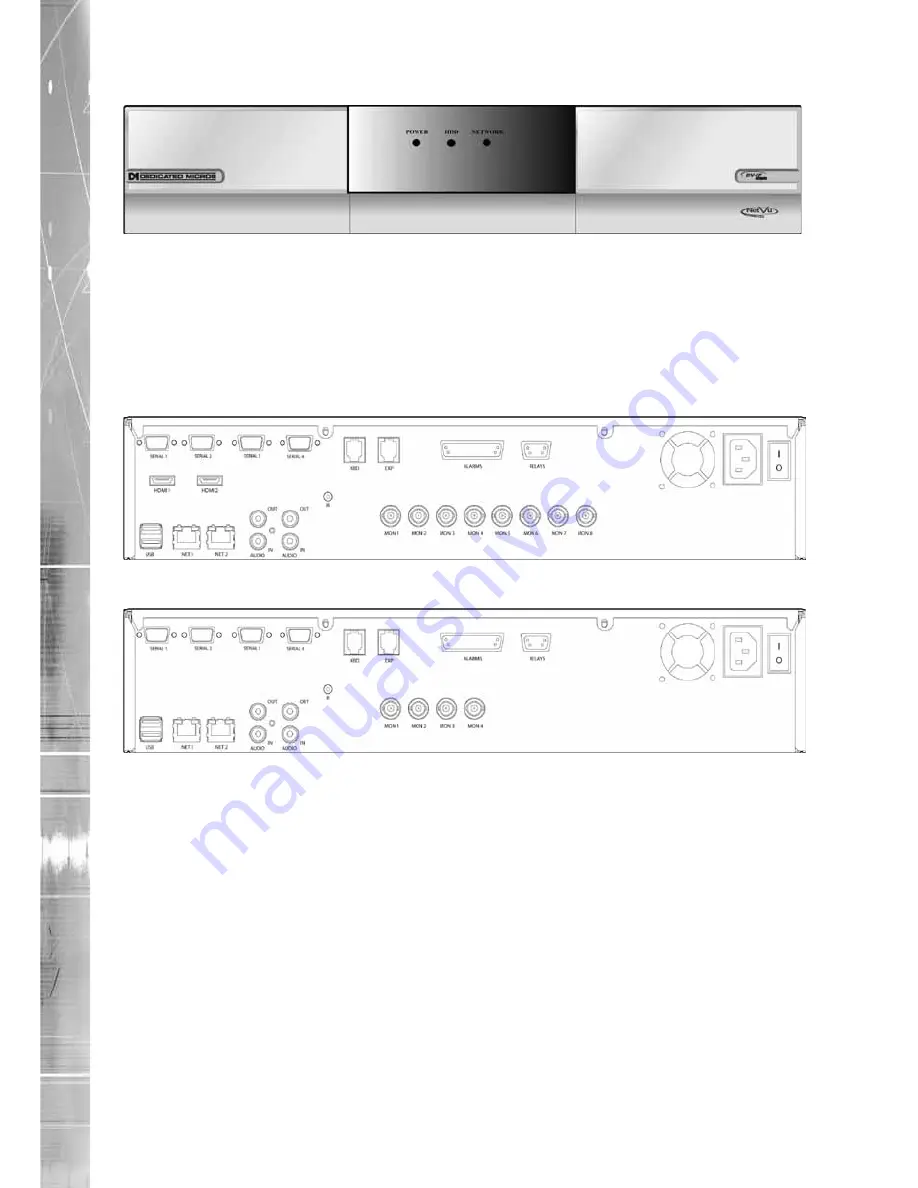
Front Panel connections
Data
LED’s
Power
- The Power LED will be green to indicate power is connected to the unit
HDD
(Hard Disk Drive) - This will flash when images are being stored to the hard disk
Network
- The Network LED will be green to indicate a connection
Rear Panel connections
8 Input model
4 Input model
REARPANELDWGSERVER.EPS