background image

Ethernet

5.5 Connecting to a Twisted-Pair Network

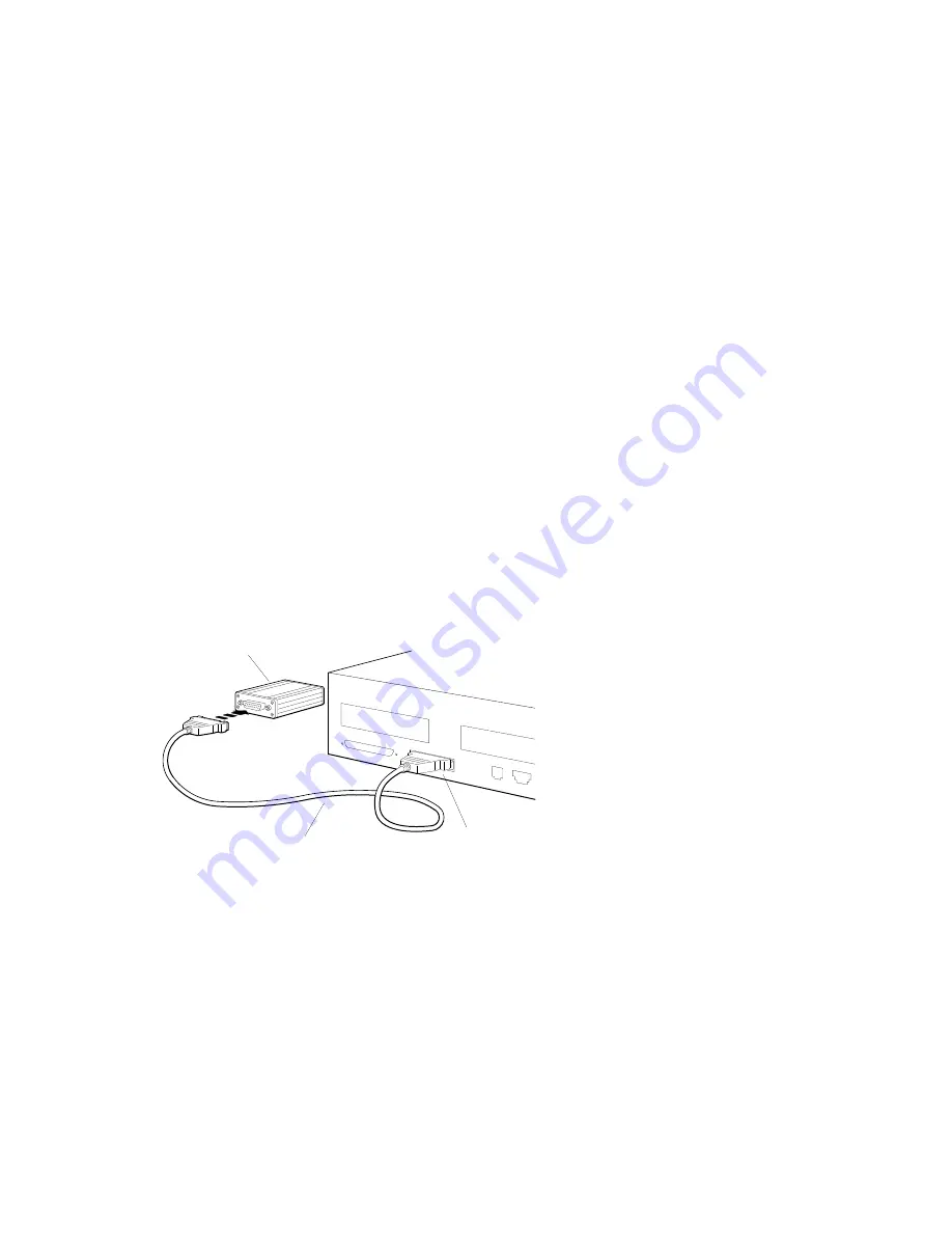
5.5.1 To Connect the ThickWire-to-Twisted-Pair Adapter

1. If necessary, unlock the sliding lock on the cable connector. (See

Section 5.2.1.)

2. Hold the ThickWire cable so that its widest part aligns with the widest

part of the ThickWire connector on the adapter.

3. Push the cable connector and the adapter connector together.
4. Push the sliding lock on the cable connector toward the connectors until it

locks them in place.

Figure 5–15 Connecting the Adapter to the ThickWire Cable

ThickWire-to-
twisted-pair adapter

WSMXS086

.

Base system
ThickWire Ethernet
connector

ThickWire Ethernet cable

Ethernet 5–15

Summary of Contents for Personal DECstation 5000

Page 1: ...Personal DECstation 5000 User s Guide Order Number EK PM30E RB 003 Digital Equipment Corporation Maynard Massachusetts...

Page 2: ...the DIGITAL logo Motif is a trademark of the Open Software Foundation Inc MS DOS is a registered trademark of Microsoft Corporation PostScript is a registered trademark of Adobe Systems Inc VELCRO is...

Page 3: ...System Unit 1 10 1 2 The Monitor 1 11 1 2 1 Connecting a Monitor to the System Unit Video Connector 1 11 1 2 2 Connecting a Monitor to a TURBOchannel Connector 1 15 1 3 The Keyboard 1 15 1 3 1 Connect...

Page 4: ...onnecting the Loopback Connector 5 2 5 2 Connecting Your Workstation to a Network 5 3 5 2 1 Using the Sliding Locks 5 3 5 3 Connecting to a ThickWire Network 5 4 5 4 Connecting to a ThinWire Network 5...

Page 5: ...tings for Using the Console Terminal 8 4 8 2 2 Operational Background Information 8 4 Part III Internal Additions to Your Workstation 9 Internal Storage Devices 9 1 Disk Drives That Digital Supports 9...

Page 6: ...art IV Workstation Management 12 Using the Console Program 12 1 Operating and Console Modes 12 1 12 2 Entering Console Mode 12 2 12 3 Console Commands 12 3 12 3 1 The Command 12 3 12 3 2 The Boot Comm...

Page 7: ...tions A 4 A 3 VRM17 Monitor Equipment Specifications A 6 A 4 LK501 AA Keyboard Equipment Specifications A 9 A 5 VSXXX BB Mouse Equipment Specifications A 11 A 6 RZ23L SCSI Hard Disk Drive Equipment Sp...

Page 8: ...onsole Command Conventions and Terms G 1 G 1 1 Conventions Used in This Appendix G 2 G 1 2 Definition of Terms G 2 G 2 Summary of Console Commands G 4 G 2 1 Command G 5 G 2 2 boot Command G 5 G 2 3 ca...

Page 9: ...3 Connecting the Monitor 1 14 1 14 LK501 Keyboard 1 15 1 15 Tilting the Keyboard 1 16 1 16 Connecting the Keyboard Cable to the Workstation 1 17 1 17 Connectors on the LK501 Keyboard 1 18 1 18 Mouse 1...

Page 10: ...wer Cord to an Expansion Box 6 11 7 1 Connectors and Adapter for Communication Devices 7 2 7 2 Connecting a 25 pin Connector 7 3 7 3 A Communications Connector Adapter 7 3 7 4 Using an Adapter to Conn...

Page 11: ...The CPU Module and the Base System Module 11 2 11 2 The CPU and its mounting posts 11 3 11 3 Releasing the lock on a mounting post 11 4 11 4 CPU module and base module connector 11 5 11 5 Attaching th...

Page 12: ...A 10 A 13 LK501 AA Keyboard Nonoperating Conditions A 10 A 14 VSXXX BB Mouse Description A 11 A 15 VSXXX BB Mouse Operating Conditions A 12 A 16 VSXXX BB Mouse Nonoperating Conditions A 12 A 17 RZ23L...

Page 13: ...unications Connectors Pin Assignments D 4 D 4 Power Supply Pin Assignments D 6 D 5 ISDN Connector D 7 D 6 SERIAL bus Pin Assignments D 8 D 7 Sound Connector D 9 D 8 Summary of Loopback Connectors D 9...

Page 14: ...onospace type Anything that appears on your monitor is set in monospace type like this Boldface type Anything that you are asked to type is set in boldface type like this Caution note Information that...

Page 15: ...Part I Introducing Your Workstation...

Page 16: ...t1 The type and number of other parts such as memory modules and internal and external storage devices will vary A basic system has 8 megabytes of memory and may include an internal hard disk drive an...

Page 17: ...wing shows the basic parts of your personal DECstation WSMXS002 SCSI terminator Power cables 2 System unit Gray scale monitor Keyboard Mouse System tool Color monitor ThickWire Ethernet loopback conne...

Page 18: ...nit Figure 1 1 The System Unit WSMXS103 The system unit is designed to sit flat on a level surface with the monitor on top of or next to it Caution Standing the system unit on its side can block the c...

Page 19: ...m unit has a green indicator light LED When you turn on your workstation the light flickers for a while as the system performs its self tests and then glows steadily once the system is up and running...

Page 20: ...slot 0 Turbochannel option slot 1 On off switch System unit power connector Monitor to system unit power connector Graphics video connector Serial communications connector Keyboard mouse connector Sou...

Page 21: ...on to a ThickWire Ethernet network or with an adapter to a ThinWire or twisted pair Ethernet network Connects the workstation to a speaker such as a small headset or the handset of a phone and a micro...

Page 22: ...touch anything inside the system unit or any item stored in an antistatic bag To use the wrist strap follow the directions on the envelope it comes in Figure 1 5 Using the Antistatic Wrist Strap WSMXS...

Page 23: ...ol that came with your workstation Insert the system tool into one of the two small rectangular holes just beneath the edge of the cover on the back of the system unit Lift up on the tool until the co...

Page 24: ...gure 1 8 Removing the Cover of the System Unit WSMXS089 6 Pivot the cover on the tabs that are along the lower part of the cover s front edge 7 When the tabs are loose in their slots lift the cover up...

Page 25: ...nnel option modules CPU module Power supply Internal drives System module Power supply Your system unit may not contain everything shown in Figure 1 9 1 1 3 2 To Close the System Unit 1 Tilt the cover...

Page 26: ...Caution Connecting or disconnecting the monitor while the power is on can damage the monitor 1 2 1 Connecting a Monitor to the System Unit Video Connector 1 Connect the monitor video cable to the mon...

Page 27: ...e Video Cable to the VRC16 Monitor B G R WSMXS007 Figure 1 11 Connecting the Video Cable to the VRM17 Monitor WSMXS013 3 Connect the other end of the monitor video cable to the video connector on the...

Page 28: ...The Five Basic Parts 1 2 The Monitor Figure 1 12 Connecting the Monitor Cable to the Video Connector on the Back of the System Unit WSMXS014 The Five Basic Parts 1 13...

Page 29: ...too 5 You can order an additional power cord and connect your monitor to a power strip or wall outlet instead of to the system unit if you want In this case you ll need to use the monitor s power swi...

Page 30: ...troubleshoot monitors connected to a TURBOchannel option module 1 3 The Keyboard The LK501 keyboard comes with your workstation Most of its keys work just like the keys on a typewriter keyboard The k...

Page 31: ...ce or it can be tilted slightly up To tilt the keyboard move the two legs on the bottom into the upright position Figure 1 15 Tilting the Keyboard Hinged feet on keyboard WSMXS010 1 3 1 Connecting the...

Page 32: ...The Five Basic Parts 1 3 The Keyboard Figure 1 16 Connecting the Keyboard Cable to the Workstation WSMXS056 The Five Basic Parts 1 17...

Page 33: ...rs on the LK501 Keyboard WSMXS097 Connectors If you want to connect your keyboard so you can use it at a distance from your system unit you may need a longer cable than the one that comes with the wor...

Page 34: ...se a mouse to move the pointer on the screen Figure 1 18 Mouse WSMXS012 Connect the mouse by plugging its cable into either of the connectors at the rear edge of the keyboard Figure 1 19 Connecting th...

Page 35: ...t power cable WSMXS099 System unit and monitor power cord Use the power cord to connect the system unit to a wall outlet or power strip Use the power cable to connect the monitor to the power outlet o...

Page 36: ...workstation must be set up in a place that meets certain requirements Caution Failure to meet these requirements can damage the equipment 2 1 1 Temperature and Humidity The temperature around the work...

Page 37: ...ectrical interference such as other terminals or monitors printers or electric pencil sharpeners To limit its exposure to static electricity and magnetized objects set up your workstation away from bu...

Page 38: ...e voltages that match your power source which is either 110 120 or 220 240 volts Devices that require matching voltages have a yellow voltage label covering the power connector This label tells you th...

Page 39: ...station 3 1 Turning On Your Workstation To turn on your workstation 1 Press the 1 on the on off switch on the back of the system unit 2 If necessary turn on your monitor If the monitor gets its power...

Page 40: ...asswd and press Return If the software has been installed on your hard disk or another storage drive and if the boot path is correctly set the boot command will start up the workstation software See S...

Page 41: ...configuration test type cnfg and press Return You ll see a display that looks something like this 3 KN02 CA DEC x1 2g TCF0 16 MB CX d 8 Sb devs 2 FDI 1 enet 08 00 2b xx xx xx SCSI 7 0 PMAG DA DEC V5 3...

Page 42: ...nd SCSI ID for each drive your system recognizes All the SCSI drives connected to the SCSI connector on the back of the system unit should be listed here The sample shows the internal hard disk with S...

Page 43: ...tape drive make sure you have the following before you begin the software installation The Guide to Installing ULTRIX The ULTRIX release notes An ULTRIX TK50 Tape Cartridge Kit or an ULTRIX CD ROM Opt...

Page 44: ...order to shut down the system This requires that you obtain superuser privileges from your system manager Enter superuser mode by typing su pressing Return and entering your password 2 Turn off any de...

Page 45: ...ugh the system unit it will go off when you turn off the system unit If the monitor is plugged into a wall outlet press the 0 on its on off switch to turn it off 5 Unplug all power cords from their po...

Page 46: ...uipment in the carton it came in Use any padding that came in the carton to hold the equipment securely in place Be sure to include the following in each carton Any cables power cords and terminators...

Page 47: ...Part II External Additions to Your Workstation...

Page 48: ...d pair Ethernet network How to find the Ethernet station address for your system The Personal DECstation is designed so that you can connect it easily to a ThickWire ThinWire or Twisted pair Ethernet...

Page 49: ...ystem self test successfully The system self test will fail if your workstation is not connected to a network and has no loopback connector installed The loopback connector comes with your workstation...

Page 50: ...nWire or Twisted pair network you ll use an adapter to make this connection 5 2 1 Using the Sliding Locks There are sliding locks on the Ethernet connector on the system unit and on one end of the Thi...

Page 51: ...ork you have To connect to a ThickWire network see Section 5 3 To connect to a ThinWire network see Section 5 4 To connect to a Twisted pair network see Section 5 5 You can also connect your workstati...

Page 52: ...t out 4 Find the ThickWire Ethernet cable Note that one end of the cable has a sliding lock on it and the other does not 5 Find the end of the cable that doesn t have the sliding lock Position it so i...

Page 53: ...h the other end of the ThickWire cable at this time Turn to Section 5 6 Report your address to your system manager who will complete the connection to the network 5 4 Connecting to a ThinWire Network...

Page 54: ...es not 5 Find the end of the cable that doesn t have the sliding lock Position it so its widest part is on top Figure 5 6 ThickWire Ethernet Cable WSMXS019 Sliding lock on Thickwire Ethernet connector...

Page 55: ...Ethernet 5 4 Connecting to a ThinWire Network Figure 5 7 Connecting the ThickWire Ethernet Cable to the System Unit WSMXS081 5 8 Ethernet...

Page 56: ...tice that the ribbed part of the T connector can be twisted from side to side Press this ribbed part onto the ThinWire connector on the adapter and turn it to the right until it slides forward and loc...

Page 57: ...n place Figure 5 10 Connecting the ThinWire Adapter to the ThickWire Cable Base system ThickWire Ethernet connector WSMXS084 ThickWire Ethernet cable 5 4 2 To Connect the Workstation to the ThinWire N...

Page 58: ...rnet cable ThickWire to ThinWire adapter Do not attach the other end of the ThickWire cable at this time Turn to Section 5 6 for instructions Report your address to your system manager who will comple...

Page 59: ...oes not 5 Find the end of the cable that doesn t have the sliding lock Position it so its widest part is on top Figure 5 12 ThickWire Ethernet Cable WSMXS019 Sliding lock on Thickwire Ethernet connect...

Page 60: ...Ethernet 5 5 Connecting to a Twisted Pair Network Figure 5 13 Connecting the ThickWire Ethernet Cable to the System Unit WSMXS081 Ethernet 5 13...

Page 61: ...adapter and the twisted pair Ethernet cable Figure 5 14 Parts for Connecting to a Twisted Pair Ethernet Network WSMXS040 Front view Back view ThickWire Ethernet connector Twisted pair phone jack type...

Page 62: ...widest part aligns with the widest part of the ThickWire connector on the adapter 3 Push the cable connector and the adapter connector together 4 Push the sliding lock on the cable connector toward t...

Page 63: ...into place Figure 5 16 Connecting the Twisted Pair Cable to the Adapter WSMXS087 ThickWire to twisted pair adapter Hold the telephone jack type of connector so the clip is on the bottom To ThickWire...

Page 64: ...splay and find the line that begins with 3 The entries that follow the 3 describe the configuration of your base system 4 Once you ve found the 3 look at the rightmost column in the display and find t...

Page 65: ...r tells you What external storage devices you can add to your basic workstation The rules for connecting SCSI devices to your workstation How to verify and assign SCSI IDs How to link storage devices...

Page 66: ...drives contained within an expansion box For a list of the drives that can be connected to your workstation see Appendix F All external storage devices are connected either by means of the SCSI connec...

Page 67: ...l extender box which has only one The second connector of the last expansion box or tabletop drive enclosure in the chain must contain the large SCSI terminator that comes with the drive The TURBOchan...

Page 68: ...e the SCSI IDs of the devices you re using and how to change these numbers if necessary 6 3 1 Factory Assigned SCSI IDs Table 6 1 shows the SCSI IDs usually preassigned to each kind of drive Table 6 1...

Page 69: ...tor on the back of the system unit should be listed here 4 Look at the column headed DEV device This column lists the device code and the SCSI ID for each listed drive In the sample the number of the...

Page 70: ...r instructions on identifying or changing the SCSI IDs on the RZ23L RZ24 and RZ25 hard disk drives see Section 9 5 1 For information about other SCSI devices refer to the guide that came with the expa...

Page 71: ...f the SCSI connectors it doesn t matter which one on the back of the expansion box a Press the two wire brackets on the expansion box connector away from the connector b Hold the cable connector so th...

Page 72: ...ou must always place it last in the chain 6 Turn on the expansion box power Then turn on the system unit 6 5 Linking Storage Devices Together You can connect up to three expansion boxes or a total of...

Page 73: ...de of the cable connector until they lock into the groves on the sides of the connector Gently press the two wire brackets on the SCSI connector away from the connector Hold the connector so the wides...

Page 74: ...Final Expansion Box Wire brackets Hold the terminator so the widest part of its connector is on top and push the terminator onto the unused SCSI connector Terminator d i g i t a l WSMXS093 d i g i t a...

Page 75: ...he power connector on each expansion box Figure 6 6 Connecting a Power Cord to an Expansion Box WSMXS095 d i g i t a l d i g i t a l d i g i t a l d i g i t a l 6 Plug the other end of each cord into...

Page 76: ...he SCSI connector on the back of the system unit should be listed here The sample shows the internal hard disk with SCSI ID 2 and a tape drive with SCSI ID 5 The column headed PID product ID lists the...

Page 77: ...ribes Communication devices such as printers plotters and modems that can be used with your workstation How to connect communication devices directly to the system unit How to use a communications con...

Page 78: ...e system unit Figure 7 1 Connectors and Adapter for Communication Devices 25 pin communications connector 25 pin communications connector adapter WSMXS042 Telephone jack type of connector 7 1 1 To Con...

Page 79: ...pin cable connector so the widest part of the connector is on top Turn the screws to your right to hold the connector in place 7 1 2 To Connect a Device with a Telephone Jack Type of Connector MMJ 1 F...

Page 80: ...nications connector adapter so its widest part is on top Hold the cable connector so the clip is to your left If your printer plotter or modem fails to work see the troubleshooting instructions in the...

Page 81: ...Terminal as the System Console The system uses the presence or absence of an LK501 keyboard to determine the console device If an LK501 keyboard is not detected during the power up self test the syst...

Page 82: ...g When performing distributed network server tasks the Personal DECstation has no need for the expensive graphics hardware usually associated with workstations so it is configured without a graphics m...

Page 83: ...ling a Console Terminal WSMXM074 1 0 Communications Communications keyboard LK201 or LK401 Alternate terminal cable terminal cable Alternate connector line adaptor Alternate console terminal Regular s...

Page 84: ...aud rate 9600 Bits 8 Parity None Stop bits 1 Flow Control Xon Xoff Mode Full duplex Once you have connected the terminal to the RS232 port you can now use the messages displayed on the terminal to per...

Page 85: ...le and diagnostic messages either on the graphics monitor or on a VT320 type terminal connected to the RS232 port located on the rear of the unit At powerup the system looks for a keyboard plugged int...

Page 86: ...Part III Internal Additions to Your Workstation...

Page 87: ...ve 209 megabytes RZ25 hard disk drive 426 megabytes The hard disk drives are SCSI devices the floppy disk drive is not Digital will make other drives available from time to time Please consult your Di...

Page 88: ...Select Number 1 Remove the drive from its metal mounting bracket and from its perforated floppy drive shield 2 The drive select switch is on the right side of the drive as you face the front of the d...

Page 89: ...n a metal mounting bracket Hold the drive so that the bracket is on the bottom Figure 9 2 Floppy Disk Drive and Mounting Bracket Mounting bracket WSMXS046 5 Connect the FDI cable to the drive 6 Connec...

Page 90: ...and the Internal Drive Power Cable to the Floppy Disk Drive WSMXS057 7 Stand facing the front of the system unit The space for the drive is in the right front corner Fit the tabs on the left side of...

Page 91: ...drive down firmly 9 Slide the latch beside the post into the locked position 10 Connect the floppy disk interface FDI cable to the FDI connector on the base system module as shown in Figure 9 5 11 Co...

Page 92: ...9 3 Making Sure Your Workstation Recognizes the Floppy Disk Drive 1 If the workstation software is running shut it down Type shutdown h now and press Return 2 When you see the console prompt type cnf...

Page 93: ...0 on the on off switch on the back of the system unit 3 Open the system unit See Section 1 1 3 1 on page 1 6 4 Stand facing the front of the system unit The floppy disk drive is in the right front co...

Page 94: ...section gives you instructions for setting the SCSI IDs of the three most commonly used internal hard disk drives 9 5 1 To Set SCSI IDs for the RZ23L RZ24 and RZ25 The internal hard disk drive is usu...

Page 95: ...re 9 7 to set the SCSI ID The ID should be 2 unless you have another device with SCSI 2 already attached to the SCSI connector at the back of the system unit Figure 9 7 SCSI ID Jumper Settings for the...

Page 96: ...e 9 8 to set the SCSI ID The ID should be 2 unless you have another device with SCSI 2 already attached to the SCSI connector at the back of the system unit Figure 9 8 SCSI ID Jumper Settings for the...

Page 97: ...is jumper does not affect the SCSI ID number of the drive and must not be removed If the jumper is removed the drive will not function correctly The SCSI ID is factory set at 2 If you need to change t...

Page 98: ...Using the Pins on the Side of the Drive WSMXS058 SCSI ID 6 SCSI ID 1 SCSI ID 3 SCSI ID 5 SCSI ID 4 SCSI ID 2 SCSI ID 0 Front SCSI ID pins If you use the pins on the front of the drive remove all jumpe...

Page 99: ...alling a Hard Disk Drive Figure 9 10 SCSI ID Settings Using the Pins on the Front of the Drive WSMXS108 SCSI ID 3 SCSI ID 4 SCSI ID 6 SCSI ID 5 SCSI ID 1 SCSI ID 2 SCSI ID 0 Side SCSI ID pins RZ 25 dr...

Page 100: ...down Type shutdown h now and press Return 2 Turn off the workstation by pressing the 0 on the on off switch on the back of the system unit 3 Open the system unit See Section 1 1 3 1 4 The hard disk dr...

Page 101: ...wer Cable to the Hard Disk Drive WSMXS049 SCSI signal cable Power cable 7 Stand facing the front of the system unit The space for the hard disk drive is at the front of the unit in the center Fit the...

Page 102: ...stem unit Press the drive down firmly 9 Slide the latch beside the post into locked position 10 Connect the SCSI cable to the SCSI connector on the base system module 11 Connect the internal drive pow...

Page 103: ...king Sure Your Workstation Recognizes the Hard Disk Drive 1 If the workstation software is running shut it down Type shutdown h now and press Return 2 At the console prompt type cnfg 3 and press Retur...

Page 104: ...not list them correctly you may have two or more devices set to the same SCSI ID You ll need to change the ID for one of these drives before your system will work properly See Section 9 5 1 or refer t...

Page 105: ...igure 9 15 Removing a Hard Disk Drive WSMXS052 Locking post Cutouts Tabs 9 Disconnect the SCSI cable from the drive 10 Disconnect the drive power cable from the drive 11 Replace the cover of the syste...

Page 106: ...your system to as much as 40 megabytes 10 1 Adding Memory to Your Workstation Caution Touching the contacts that run along the bottom of a memory module can damage or destroy the module Caution Don t...

Page 107: ...hips on one side of this module 1Do not confuse the etched part number with the module part number which has the prefix form 54 xxxxx xx or 57 xxxxx xx 2The 54 21213 01 MS01L AA memory module can be u...

Page 108: ...21 Front view Back view XXXXXXX XX Notch 2 Mbyte SIMM Etch part number in the center On the 8 megabyte module the etched part number is on the top left corner on the front of the module You are lookin...

Page 109: ...1 Adding Memory to Your Workstation Figure 10 2 Identifying 8 megabyte Memory Modules WSMXM022 Front view Back view Notch XX XXXXX XX 8 Mbyte SIMM Etch part number at the end farthest from the notch 1...

Page 110: ...Your system won t work properly if you mix the two types 10 1 2 To Install Memory Modules 1 If the workstation software is running shut it down type shutdown h now and press Return 2 Turn off the sys...

Page 111: ...lled in pairs See Table 10 2 Install the left module of the pair first then the right Keeping your fingers away from the contacts that run along the bottom of the memory module hold the module so that...

Page 112: ...our system unit 2 If your workstation software is set to start automatically shut it down Type shutdown h now and press Return 3 When you see the console prompt type cnfg 3 and press Return You ll see...

Page 113: ...epresentative for help 10 2 Removing Memory from Your Workstation 1 If the workstation software is running shut it down type shutdown h now and press Return 2 Turn off the system unit by pressing the...

Page 114: ...ds of the connector until you can feel them release Figure 10 6 Releasing the Latches on a Slot Connector WSMXS054 6 Tilt the memory module toward the front of the system unit until you can lift it ou...

Page 115: ...ove and install CPU modules How to test CPU modules The CPU module and the base system module in combination provide the computing power of your workstation Your workstation can use any of these three...

Page 116: ...egahertz 54 20615 02 54 21337 021 KN02 CC 33 megahertz 54 21331 01 KN02 DA 1These are the newer plastic as opposed to ceramic parts they are functionally equivalent to the earlier variety listed The C...

Page 117: ...system unit by pressing the 0 on the on off switch on the back Unplug the system unit power cord 3 Open the system unit See Section 1 1 3 1 4 Put on the antistatic wrist strap See Figure 1 5 5 Locate...

Page 118: ...the posts on the other two locks Caution Avoid touching the heat sinks on the CPU module they break easily Figure 11 3 Releasing the lock on a mounting post Lock CPU module Mounting posts WSMXS033 Hea...

Page 119: ...odule connector Heat sinks 11 2 Installing a CPU Module 1 If necessary open the system unit See Section 1 1 3 1 2 Put on the antistatic wrist strap See Figure 1 5 3 Keeping your hands well away from t...

Page 120: ...corner holes onto its corresponding mounting post Figure 11 5 Attaching the CPU module WSMXS035 CPU connector Base module connector Holes one of three Mounting posts one of three 6 Replace the cover o...

Page 121: ...3 misc cpu type s code NDX 102A The NDX 102A at the end of the message tells you that you have a 33 megahertz CPU If your workstation fails to recognize the CPU you have just installed Check to make...

Page 122: ...Part IV Workstation Management...

Page 123: ...ou ll use your workstation in operating mode that is you ll use the workstation software for tasks like these Creating and revising files letters charts spreadsheets and so on Backing up files Sending...

Page 124: ...ssword see Section 12 3 4 12 2 Entering Console Mode You can enter console mode in any of these ways If the workstation software is running shut it down by typing shut down h now and pressing Return N...

Page 125: ...ay 12 3 1 The Command Use the command to display a list of available console commands and their formats Give the command by typing and pressing Return 12 3 2 The Boot Command The boot command tells yo...

Page 126: ...ck the configuration display for the device name and slot number 2 Using the slot number and device name you determined in step 1 type setenv boot slot number device name vmunix a and press Return 3 T...

Page 127: ...n Existing Password Type passwd and press Return At the pwd prompt enter the existing password and press Return When the console prompt appears type passwd c and press Return The system removes the pa...

Page 128: ...entire list of environment variables type printenv and press Return To display an individual environment variable type printenv replace variable with the name of the environment variable you want to...

Page 129: ...w to interpret video error messages How to connect and use an alternate terminal The powerup self test sequence and the LED display How to perform minimum configuration troubleshooting with the system...

Page 130: ...the system is operational 2 Troubleshooting with the alternate video Some failures can prevent the system from displaying error messages on the graphics monitor In this case connect a VT320 terminal...

Page 131: ...Part 12 22196 02 and the SCSI terminator Part 12 29635 01 If nothing is connected to these ports the system may report false errors The Ethernet diagnostics used by pst t actually send data out onto...

Page 132: ...and was specifically the controller Finally the diagnostic identified the module as the KN02 CA Figure 13 1 Example of TURBOchannel Error Message Format TFL 3 scsi cntrl 3 cntxfr KN02 CA INDICATES TH...

Page 133: ...SIMMs ni Ethernet Base module Enet card Enet peripherals rtc Real time clock Base module scc RS232 Base Module RS232 peripherals scsi Scsi Base Module SCSI card SCSI peripherals Table 13 2 Identificat...

Page 134: ...ages to the graphics monitor If however no keyboard is detected on the SERIAL bus all text will be sent directly to the RS232 port Connect your terminal to the 25 pin RS232 connector and set your term...

Page 135: ...The default power up console assignment can be defeated by issuing the following console command setenv console s You can switch your console back to your graphics monitor with the command setenv con...

Page 136: ...d as well as all memory modules You can then run the power up self test and interpret the flashing system LED to isolate and correct problems with this core system The keyboard and video sub system ca...

Page 137: ...er up sequence By interpreting these flashes you can determine which pieces of the unit are operational and then deduce which modules are not functional It is important to watch the LED closely during...

Page 138: ...ashes will be displayed if a problem is encountered using the memory contained on the base module When the system reaches the point where text will be displayed on the default console device the LED w...

Page 139: ...CONTINUOUS LONG FLASHES see Table 13 5 LED STAYS OFF FOR MORE THAN 60 SECONDS see Table 13 5 1 LONG LED FLASH FOLLOWED BY EITHER 1 short LED flash or 2 short LED flashes see Table 13 5 LED STAYS ON se...

Page 140: ...ASIC could be at fault Check power supply swap CPU swap base module Table 13 5 Interpreting Diagnostic LED Indicator During First 30 Seconds After Power Up Firmware Initialization Period LED Function...

Page 141: ...been installed Table 13 6 Interpreting Diagnostic LED Indicator During 2nd 30 Seconds Following First Video Power Up Self Test Period LED Function Meaning Corrective Action LED stays on continuously F...

Page 142: ...communications connector Keyboard mouse connector Sound connector Base system ThickWire Ethernet connector Base system SCSI connector 1 2 3 4 5 6 7 8 9 10 11 1 2 3 4 5 6 7 8 9 10 11 If the loopback c...

Page 143: ...Part V Appendices...

Page 144: ...erating conditions and nonoperating conditions for the following equipment Personal DECstation 5000 VRC16 monitor VRM17 monitor LK501 keyboard VSXXX BB mouse RZ23L hard disk drive RZ24 hard disk drive...

Page 145: ...123 watts maximum Table A 2 System Unit Operating Conditions Temperature range1 10 C to 40 C 50 F to 104 F Temperature change rate 11 C 52 F per hour maximum Relative humidity 10 to 90 noncondensing M...

Page 146: ...pecifications Table A 4 Acoustics Preliminary Declared Values per ISO 9296 and ISO 7779 LWAd LpAm operator position Idle 4 5 bels 36 dBA Operating 4 5 bels 36 dBA Current values for specific configura...

Page 147: ...shadow mask black matrix screen 0 26 mm maximum triad pitch 90 deflection angle 3 color Silica antiglare treatment purity shielding dynamic focus correction Display characteristics 1024 by 768 pixels...

Page 148: ...nsumption 150 watts maximum Table A 6 VRC16 Monitor Operating Conditions Temperature range 1 10 C to 40 C 50 to 104 F Relative humidity 10 or less to 95 Maximum wet bulb temperature 32 C 89 F Minimum...

Page 149: ...Power switch Power indicator High scan low scan switch Cathode ray tube CRT 483 mm 431 8mm 17 in diagonal Monochrome high efficiency type phosphor Display characteristics 1280 pixels by 1024 lines hi...

Page 150: ...ync pulse 1 2232 s high scan and 1 7211 s low scan Vertical rate timing Back porch 0 427864 ms high scan and 0 3834 ms low scan Blanking interval 0 505658 ms high scan and 0 5054 ms low scan Front por...

Page 151: ...imum wet bulb temperature 28 C 82 F Minimum dew point temperature 2 C 36 F Altitude 2400 m 8000 ft maximum 1Reduce maximum temperature by 1 8 C for each 1 000 meter 1 0 F for each 1 000 ft increase in...

Page 152: ...cm 19 00 in Depth 19 20 cm 7 56 in Number of keys 108 Number of indicators 2 status LEDs Language variations 15 Software selectable keycaps required Cable 1 8 m 6 ft uncoiled length 4 pin mmj connecto...

Page 153: ...32 C 90 F Minimum dew point temperature 15 C 60 F Altitude 2 400 m 8 000 ft maximum 1Reduce maximum temperature by 1 8 C for each 1 000 meter 1 0 F for each 1 000 ft increase in altitude Table A 13 LK...

Page 154: ...onnector male Accuracy 3 0 to 24 5 cm 0 to 10 in per second in any direction 15 24 5 to 49 cm 10 to 20 in per second in any direction 30 49 to 73 5 cm 20 to 30 in per second in any direction Baud rate...

Page 155: ...8 C 82 F Minimum dew point temperature 2 C 36 F Altitude 2 400 m 8 000 ft maximum 1Reduce maximum temperature by 1 8 C for each 1 000 meter 1 0 F for each 1 000 ft increase in altitude Table A 16 VSXX...

Page 156: ...1 20 lb Height 2 54 cm 1 00 in Width 10 16 cm 4 00 in Depth 14 61 cm 5 75 in Capacity Bytes per drive 121 65 MB Blocks per drive 237 588 Block size 512 bytes Data transfer rate Bus asynchronous mode 3...

Page 157: ...F Minimum dew point temperature 2 C 36 F Altitude 300 to 4600 m 1000 to 15 000 ft 1Reduce maximum temperature by 1 8 C for each 1 000 meter 1 0 F for each 1 000 ft increase in altitude Table A 19 RZ23...

Page 158: ...70 lb Height 4 14 cm 1 63 in Width 10 16 cm 4 00 in Depth 14 61 cm 5 75 in Capacity Bytes per drive 209 7 MB Blocks per drive 409 802 Block size 512 bytes Data transfer rate Bus asynchronous mode 3 0...

Page 159: ...inimum dew point temperature 2 C 36 F Altitude 300 to 4600 m 1000 to 15 000 ft 1Reduce maximum temperature by 1 8 C for each 1 000 meter 1 0 F for each 1 000 ft increase in altitude Table A 22 RZ24 SC...

Page 160: ...lb Height 4 14 cm 1 63 in Width 10 16 cm 4 00 in Depth 14 61 cm 5 75 in Capacity Bytes per drive 426 MB Blocks per drive 832 527 Block size 512 bytes Data transfer rate Bus asynchronous mode 3 0 MB p...

Page 161: ...erature 26 C 78 F Altitude 300 to 3050 m 1000 to 10 000 ft 1Reduce maximum temperature by 1 8 C for each 1 000 meter 1 0 F for each 1 000 ft increase in altitude Table A 25 RZ25 SCSI Hard Disk Drive N...

Page 162: ...cording surfaces per diskette 2 MFM data bit rate 250 500 1000 kHz Sectors per track 9 double density 18 high density 36 extra density Capacity 2 88 KB Bytes per drive 737 280 double density 1 474 560...

Page 163: ...aximum wet bulb temperature 25 6 C 78 F Altitude 300 to 3050 m 1000 to 10 000 ft maximum 1Reduce maximum temperature by 1 8 C for each 1 000 meter 1 0 F for each 1 000 ft increase in altitude Table A...

Page 164: ...ignal also runs to a small speaker within the system enclosure not externally visible You may connect the 4 wire modular jack to any 4 wire modular jack telephone handset or headset though Digital rec...

Page 165: ...For order information on multimedia kits refer to Table B 1 and Table B 2 Table B 1 XMedia Software Kits Order Number Description QA MB4AA H5 CDC XMedia Tools Software TK50 Includes both the runtime k...

Page 166: ...on 5000 TX frame buffer with XMedia Tools Runtime licenses AV10U DA DECvideo PIP Upgrade from TX to DECvideo IN Includes option card for TX 24 plane color frame buffer attaches to TX TURBOchannel grap...

Page 167: ...ists part numbers for the Personal DECstation 5000 Basic System Components SCSI and Floppy Disk Hardware Monitors Input Devices Cables Connectors Adapters and Terminators Miscellaneous Hardware Multim...

Page 168: ...ules 4Mb pair two 2Mb SIMMs MS01 AA MS01L AA2 Memory module SIMM 8Mb single 57 34320 01 Memory modules 16Mb pair two 8Mb SIMMs MS01 CA System unit cover 70 28353 01 System unit chassis 74 44241 01 1Th...

Page 169: ...or 12 30552 01 Internal SCSI cable 17 01626 04 RZ23L half height hard disk drive RZ23L E RZ23L FL RZ24 hard disk drive RZ24 E RZ24 FL RZ24 hard disk drive PCB 29 28144 01 RZ25 hard disk drive RZ25 E R...

Page 170: ...VRC16 16 inch color monitor 120 240 volts Southern Hemisphere VRC16 C4 VRM17 17 inch gray scale monitor 120 240 volts Northern Hemisphere VRM17 AA VRM17 17 inch gray scale monitor 120 240 volts Southe...

Page 171: ...0 SCSI system unit to expansion box cable 17 02641 01 BC09D 03 ThickWire transceiver cable 17 01321 01 BNE4C 02 ThinWire cable 12 ft 17 01241 12 BC16M 12 Video cable color 17 02906 01 BC29G 09 Video c...

Page 172: ...26 01 SCSI chain terminator 12 30552 01 12 30552 01 ThinWire T connector 12 25869 01 H8223 00 ThinWire terminators 12 26318 01 Jumper to clear NVR 12 14314 00 12 14314 00 Comm line to MMJ adapter 12 3...

Page 173: ...cable1 17 03089 01 DECaudio distribution box1 70 28758 01 DECaudio power supply1 30 35431 01 AC cable for power supply 17 00606 10 DECvideo IN 66Hz TX DECvideo PIP AV10A AA DECvideo IN 72Hz TX DECvide...

Page 174: ...Pin Assignments This appendix lists pin assignments for the following connectors SCSI EIA RS232 ThickWire Ethernet Power supply ISDN Sound SERIAL bus Modem loopback Ethernet loopback Connector Pin Ass...

Page 175: ...GND 46 C D 45 GND 44 SEL 43 GND 42 MSG 41 GND 40 RST 39 GND 38 ACK 37 GND 36 BSY 35 GND 34 GND 33 GND 32 ATN 31 GND 30 GND 29 GND 28 RSVD 27 RSVD 26 TERMPWR 25 NC 24 RSVD 23 RSVD 22 GND 21 GND 20 GND...

Page 176: ...ignments Pin Source Signal Description 1 Shield 2 XCVR ACOL Collision presence 3 KNO2 ATX Transmission 4 GND Ground 5 XCVR ARX Reception 6 XCVR GND Power return 7 CTL Control output 8 GND Ground 9 XCV...

Page 177: ...Transmitted data 3 DCE RxD 104 BB Received data 4 DTE RTS 105 CA Request to send 5 DCE CTS 106 CB Clear to send 6 DCE DSR 107 CC Data set ready 7 GND 102 AB Signal ground 8 DCE CD 109 CF Carrier dete...

Page 178: ...iption 20 DTE DTR 108 2 CD Data terminal ready 21 Unconnected 22 DCE RI 125 CE Ring indicator 23 DTE DSRS 111 CH Data signal rate select 24 Unconnected 25 Unconnected 1Comite Consultatif International...

Page 179: ...n Assignments D 4 Power Supply Pin Assignments Table D 4 Power Supply Pin Assignments Pin Signal 1 Speaker 1 2 DCOK 3 5 1V 4 GND 5 5 1V 6 GND 7 12 1V 8 Speaker 2 9 System OK LED 10 GND 11 5 1V 12 GND...

Page 180: ...8 No connection D 6 SERIAL bus The SERIAL bus uses a 4 pin shielded MOLEX SEMCONN or AMP SDL modular type connectors The MOLEX version will be unkeyed The AMP version will have key D This provides com...

Page 181: ...Connector Pin Assignments D 6 SERIAL bus Table D 6 SERIAL bus Pin Assignments Pin Signal Function 1 GND Ground 2 SDA Serial data 3 SCL Serial clock 4 12V 12 Volts D 8 Connector Pin Assignments...

Page 182: ...1 Audio In 1 Audio input 2 Audio Out 1 Audio output 3 Audio Out 2 Audio output 4 Audio in 2 Audio Input ground D 8 Loopback Connector Pin Assignments Table D 8 Summary of Loopback Connectors Function...

Page 183: ...oopback Connector Pin Assignments Part 12 15336 13 Option H3200 From Pin No Signal To Pin No Signal P4 2 TX2 P4 3 RX2 P4 4 RTS2 P4 5 CTS2 P4 6 DSR2 P4 20 DTR2 P4 12 SPDMI2 P4 23 DSRS2 P4 18 LLPBK2 P4...

Page 184: ...tion on the Personal DECstation 5000 workstation that is required by the United Kingdom The Personal DECstation 5000 workstation is manufactured by Digital Equipment Corporation The model number of th...

Page 185: ...PTO BT1 Hull2 MCL3 CCITT 2400 ISO 2110 V 24 V 28 Yes Yes Yes Recommend 4800 Yes Yes Yes 1 X 21bis 9600 BS 6623 Cable Yes Yes Yes 19200 Part 1 1985 BC22F 10 BC22F 25 No No Yes 1BT British Telecommunica...

Page 186: ...isolation to satisfy the requirements of the relevant parts of standard BS6301 Any product connected to these ports must meet one of the following conditions Be covered by OFTEL s General Approval NS...

Page 187: ...d Table E 2 Clearance and Creepage Specs for PMBA AA Clearance Xmm Creepage Ymm Voltage1 2 0 2 4 3 8 up to 50 2 6 3 0 4 8 up to 125 4 0 5 0 8 0 up to 250 4 0 6 4 10 0 up to 300 1Used or generated by o...

Page 188: ...uit PTT If any apparatus including cable or wiring is to be connected between the approved apparatus and the point of connection to any particular digital circuit then all the other apparatus must con...

Page 189: ...tus Between the Approved Apparatus and a Digital Circuit PTT Figure E 1 System Module J Connector Locations WSMXP004 J2 J3 J4 J5 J7 J1 J6 E22 E35 E37 J28 J17 J16 J31 J29 J30 J32 J55 J33 J56 J54 J57 J5...

Page 190: ...is list please contact your Digital sales representative In the SZ12 expansion box Floppy disk drives RX23 1 4 megabytes RX33 1 2 megabytes 3 1 2 inch hard disk drive RZ25 426 megabytes 5 1 4 inch har...

Page 191: ...tes Tape drives TZK10 525 megabytes CD ROM drives RRD42 600 megabytes Tabletop drives Tape drives TK50Z 95 megabytes TSZ05 1600 bpi nine track tape TSZ07 1600 6250 bpi nine track tape TLZ04 1 2 gigaby...

Page 192: ...no leading zeros for example 123 Enter octal values as a string of octal digits with a leading zero for example 0177 Enter hexadecimal values as a string of hexadecimal digits preceded by 0 and a lowe...

Page 193: ...play these variables in all capital letters Arguments enclosed in square brackets are optional Ellipses follow an argument that can be repeated A vertical bar separates choices You can think of the ba...

Page 194: ...also contain other test scripts are commonly used for troubleshooting the system Slot The physical location of a module or modules TURBOchannel option modules occupy slots 0 and 1 The base system occ...

Page 195: ...s environmental variables Sets system parameters unsetenv Removes environmental variables Sets system parameters passwd Sets console password Sets system parameters t Lists out test for slot Lists Dia...

Page 196: ...arameter to have the system wait a certain number of seconds before starting Replace seconds with the number of seconds the system should wait before starting Include the optional n parameter to have...

Page 197: ...a SCSI option module in slot 1 type boot 1 tz5 vmunix and press Return To perform a multiuser boot operation include the a argument If you omit the a argument the system performs a single user boot To...

Page 198: ...base system module is slot 3 script name is the name of the script for which you want to display the contents G 2 4 cnfg Command Use the cnfg command to display hardware configuration information The...

Page 199: ...rting address and the number of successive addresses you want to examine Use the form address low count to specify the addresses where you store values When you type this address range format replace...

Page 200: ...init command to initialize module hardware The init command format is init slot number m Keep the following points in mind about the init command To initialize the entire system specify the init comm...

Page 201: ...password After the console prompt appears type passwd c and press Return The system then removes the password requirement To set a new password include the s parameter Enter the new password at the p...

Page 202: ...about the script command When you type the script command replace name with the name you are giving the script Then press Return After you press Return type the commands you want to include in the sc...

Page 203: ...le If the console variable is set to anything other than s the monitor connected to the graphics module in the lowest numbered slot is enabled If no graphics module is installed and the keyboard is co...

Page 204: ...on Specifies the type of power up self test the system runs Specify q to run a quick test when the power up self test runs Specify t to run a thorough test when the power up self test runs Specifies t...

Page 205: ...orough power up self test script for a SCSI controller and drives in slot 2 type sh 2 pst t and press Return G 2 16 t Command Use the t command to run individual tests The t command format is t l slot...

Page 206: ...and to remove environment variables Table G 2 earlier in this appendix lists the environment variables you can set The unsetenv command removes a standard environment variable except osconsole and dur...

Page 207: ...ompts 3 2 console terminal 7 4 to activate 7 5 CPU modules CPU modules cont d differentiating 20 megahertz and 25 megahertz 11 2 heat sinks 11 4 installing 11 5 removing 11 3 testing 11 6 D dial box 1...

Page 208: ...g in screen 3 5 loopback connector 3 2 5 2 to install 5 3 M memory modules differentiating 2 mb and 8 mb 10 2 removing 10 8 to install 10 5 verifying 10 7 monitor as system console 7 5 color 1 11 conn...

Page 209: ...3 2 printenv command 12 6 S SCSI connector 6 3 SCSI devices 6 2 guidelines for connecting 6 3 linking 6 8 verifying 6 12 SCSI IDs 6 3 6 4 changing 6 6 SCSI IDs cont d factory assigned 6 4 for device c...

Page 210: ...oltage requirements 2 1 VRC16 monitor 1 11 VRM17 monitor 1 11 W workstation dismantling 4 1 increasing memory 10 1 turning off 3 6 workstation software halting 12 2 workstation software booting factor...

Reviews: